


4
DPLS1 Drain Panel Level Sensor/Control
Protected under one or more patents
© 2011 Mitsubishi Electric & Electronics USA, Inc.
U
L
U
L
DPLS1 Drain Pan Level Sensor/Control
Protected under one or more patients
© 2011 Mitsubishi Electric / HVAC
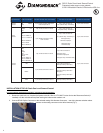
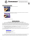
Fig 7
7. Disconnect indoor unit power before proceeding to the next step.
8. Determine the best location for the DPLS1 Water Sensor. Make sure that power has been disconnected. Find the drain pan
below the coil in the indoor unit. It is located directly below the aluminum fins of the coil and is slightly wider than the coil
depending on the style of indoor unit.
9. Wipe all water, dirt and dust from the drain pan with a damp cloth. DO NO
T REMOVE DOUBLE SIDED TAPE ON WATER
SENSOR YET. Temporarily locate the Water Sensor in the drain pan.
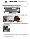
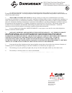
10. Rotate the panel clips on the Water Sensor so that the clips are towards the front of the indoor unit and slide onto the front
edge of the drain pan (Fig 8). Push the panel clips all the way down onto the plastic drain pan then push the Water Sensor
down until it stops on, or close to, the bottom of the drain trough (Fig 9)*.
Fig 8 Fig 9
11. Temporarily reassemble the front cover of the indoor unit to make sure that it reattaches properly. If there is interference
with the front cover, relocate the Water Sensor on the drain pan and recheck clearances.
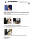
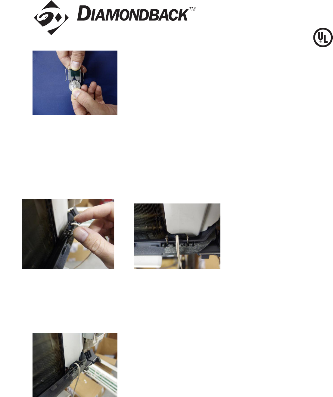
12. Once the best location has been determined, remove the double-sided tape on the Water Sensor and reinstall it in the same
manner as described ab
ove. Ensure the Water Sensor touches the bottom of the trough and the panel clips are pushed all
the way down on the front edge of the trough (Fig 10).
*These installation instructions are typical for all wall mounted, floor standing, ceiling recessed, ceiling concealed, and
ceiling suspended units. Location of the water sensor should at the drain pan no less than 3/8” from the bottom .
Fig 10
13. Bundle and tie wrap excess wire. Locate and anchor the excess wire bundles so that they do not interfere with the
reassembly of the cover of the indoor unit.
14. Reassemble the indoor unit cover.
15. Turn power on to indoor unit.