


WR44 Series Installation Guide
4
terminal equipment and power supply. A complete reference guide to the software
features that are available on the product is available separately in PDF format which can
be downloaded from the Digi International website (www.digi.com
).
All models in the WR44 range feature:
♦ 4 x 10/100Base-T Ethernet port
♦ 1 x RS232 asynchronous serial port (9-way D connector)
♦ 1 x USB 2.0 host port
♦ 2 x SIM sockets
♦ Optional Wireless LAN interface
All models may also be purchased with one of a number of hardware options which are
listed in the section entitled “Optional Features” below.
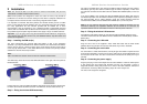
Package Contents
When you receive the router carefully unpack it and check the contents. These should
include:
♦ WR44 system unit
♦ 12V DC 1.5A mains adapter (100V-230VAC, 50–60Hz, 0.6A max.)
♦ this Installation Guide
♦ 1 x 2M CAT5 STP (Shielded, Twisted Pair) LAN cable
♦ 1 x WWAN stub antenna (2 x with the WR44–U model)
♦ 2 x WLAN antenna (if WLAN option fitted)
If any item is missing or damaged, please contact your supplier. You should also make a
record of any damage that may have occurred during shipping and report it to the carrier.
If you have ordered one of the available hardware options the package will also contain
additional cables/antennas as appropriate.
WR44 Series Installation Guide
5
1 Introduction
WR44 series routers are compact IP routers that facilitate the transmission of data over
different types of “cellular” networks depending on the model.
The routers can be configured either by using commands entered at the serial port (much
like a modem), or via the built-in Web interface. We recommend that you use the Web
interface whenever possible.
In addition to many standard LAN and Internet protocols such as PPP, the WR44 series
products provide a combination of powerful but easy to use configuration, management
and diagnostic tools. This makes them simple and cost-effective solutions for migrating
existing terminal or telemetry equipment, which use wired networks (PSTN, ISDN, etc.), to
wireless operation.
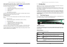
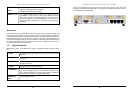
1.1 Front Panel Features
The front panel of the unit incorporates the USB host connector, 13 LED indicators and
the two SIM card-holders as shown in the following illustration:
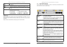
USB Host Connector
The USB host connector may be used to connect compatible USB 2.0 client devices such
as memory sticks, serial adapters, etc. Note that the total current available to power USB
devices is 0.5A.
Status Indicators
The status indicators operate as follows:
ON
Illuminates steady when power is applied.
LAN 0, 1, 2, 3
Illuminates steady when there is a network connection to the LAN
port and flashes when data is transmitted or received.
WLAN
Flashes to indicate that data is being transferred over the wireless
LAN network.
DTE
Illuminates steady if a terminal is connected to the ASY0 serial
port and the DTR signal is on. Flashes when data is transmitted or
received.