


WR44 Series Installation Guide
10
2 Installation
Note: You will not be able to use the router for remote communication until you have
subscribed to a suitable wireless network service.
WR44 series products are designed for indoor use (office or home). They should be
positioned on a smooth, level surface making sure that there is adequate ventilation. Do
not expose them to extremes of heat or cold, strong magnetic fields or liquids.
It is important to remember that these products are wireless devices just like a mobile
phone, so they will only operate reliably if there is a good quality signal from the network.
For many applications the stub antenna provided will be suitable but in some
circumstances it may be necessary to use a window-mounted or magnetically mounted
antenna with an extended cable to allow the antenna itself to be positioned to provide the
best possible signal reception. Digi International can supply a range of suitable antennas.
Important: If you are going to be using the Sar/OS Connection Wizard to configure the
unit’s Ethernet port and also connect it to your GSM/3G network, skip this section and
proceed to Configuration.
Step 1 - Installing the SIM card(s)
The router incorporates two separate SIM card holders so that if your application
demands it, you may install SIMs for two different networks. This means that one wireless
service may be used as a back-up service in the event that the primary service fails in
some way. By default, SIM 1 is the default SIM used for access to the primary network
and SIM 2 is used for the back-up network.
Note:
SIM 1 and SIM 2 can NOT be used to access two networks simultaneously.
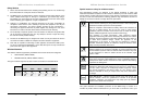
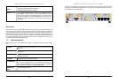
The SIM card(s) should be inserted into SIM cardholders on the right of the front panel as
illustrated below.
In both cases, the end of the SIM card with the chamfered corner should be inserted first.
For SIM 1 the contacts should be face down. For SIM 2 the contacts should be face up.
Step 2 – Fitting the wireless WAN antenna(s)
WR44 Series Installation Guide
11
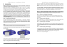
The router is supplied with a “stub” antenna suitable for with the model you have ordered.
Alternatively you may have ordered a different type of antenna separately. In either case
this should be screwed onto the SMA connector labelled ANT. WWAN (Main) on the rear
panel.
If you have a WR44-U, the unit will come with two WWAN antennas. When both of these
are fitted the operation over the wireless network may be improved, especially in areas of
low signal strength. This is called “diversity” mode. The second antenna should be
screwed onto the SMA connector labelled ANT. WWAN (Aux.) on the rear panel.
Note: If you use antennas other than the stub antennas supplied as standard (e.g. two
wall-mount antennas), the separation between the two should be no less than the
separation between the two associated connectors on the rear panel of the unit.
Step 3 – Fitting the wireless LAN antennas
If the Wireless LAN option is fitted, the unit will come with two WLAN antennas. These
should be screwed onto the male SMA connectors labelled ANT. WLAN (Main) and ANT.
WLAN (Aux.).
Step 4 – Connecting the LAN cable
Plug one end of one of the supplied 2 metre CAT5 STP cable into the RJ45 socket
labelled LAN 0. Plug the other end into the LAN socket on your PC or notebook.
Step 5 – Connecting the serial cable
For connection to a serial terminal device, a 9-way D-type serial cable is required and can
be purchased separately. Connect one end of the cable into the socket labelled ASY 0 on
the rear panel of the router. The other end would be connected to the serial port on your
terminal.
Step 6 – Connecting the power supply
Plug the jack plug on the mains adapter into the socket labelled 11-58V DC. When power
is first applied, the ON indicator will illuminate and the unit will initiate a series of
diagnostic self-tests. During this process one or more of the other indicators, will flash to
show that the unit is busy. When the flashing stops, the unit is ready to use.
The unit is now ready to be configured.