


10
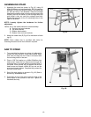
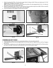
ASSEMBLING STAND
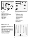
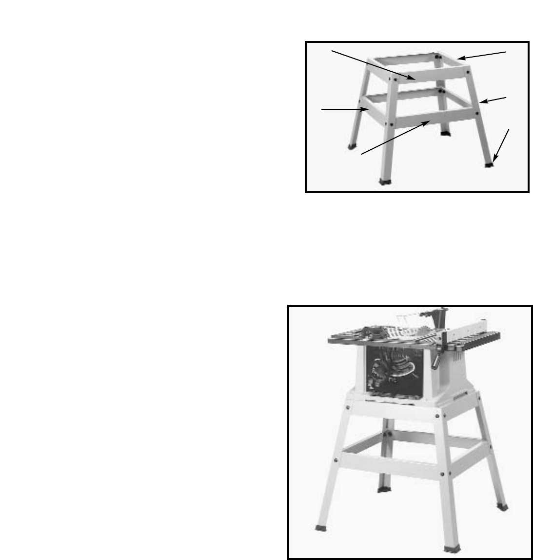
1. Assemble the stand as shown in Fig. 4C, using 16
M8x1.25x20mm carriage head bolts, 3/8" flat washers
and M8x1.25 hex nuts. Align the holes in the stand legs
(F) with the holes in the brackets. Insert the carriage
head bolt through the hole in the leg and the hole in the
bracket, place a flat washer on the carriage head bolt
and thread a hex nut onto the carriage head bolt.
Repeat this process for the 15 remaining holes in the
legs and brackets.
NOTE: Loosely tighten the hardware for further
adjustment.
Letters are on the stand brackets to ease assembly:
A - Top front and rear brackets
B - Top side brackets
C - Bottom side brackets
D - Bottom front and rear brackets
2. Attach the rubber feet (E) Fig. 4C to the bottom of each
leg (F).
NOTE: Each rubber foot is provided with holes for
mounting the stand to the floor surface if required.
Fig. 4C
B
A
C
F
E
D
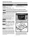
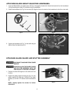
Fig. 4D
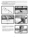
SAW TO STAND
1. Turn saw table face down on a piece of cardboard to
protect the table surface. Place stand upside down
onto saw and align the four holes in the stand with
the mounting holes in the saw.
2. Place a 3/8" flat washer on a M8x1.25x40mm hex
head screw. Insert the hex head screw through the
mounting hole in the saw and the mounting hole in
the stand. Place another 3/8" flat washer on the hex
head screw and thread a M8x1.25 hex nut on the
screw and loosely tighten. Complete this process for
the other three holes.
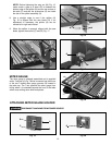
3. Stand the saw upright, as shown in Fig. 4D (Saw is
shown fully assembled here).
4. Push down on top of the saw so that the legs of the
stand adjust to the surface of the floor. Tighten all
hardware securely.