


Drawing Number: 21082
Revision: NR
OPERATION MANUAL FOR
MICROPHONE
Series 103A
1
1.0 DESCRIPTION
The Series 103A microphones are high-sensitivity
pressure sensors featuring miniature size, built-in
solid state electronics and acceleration compensation.
The Model 103A (see installation drawing) has
pigtail leads extending radially from the side of the
unit and has a nominal sensitivity of 1500 mV/psi.
The Model 103A11 is similar in appearance and in
mode of electrical connection, but differs from the
Model 103A in that the sensitivity is nominally 500
mV/psi.
Models 103A and 103A11: ICP
®
Sound Pressure
Sensors
The Model 103A02 is similar physically to the 103A
and has similar sensitivity (1500 mV/psi), but the
electrical connection is made through a top mounted
10-32 coaxial connector.
The Model 103A12 also has the top connector like
the 103A02 but the sensitivity is 500 mV/psi.
These units are ideal for wind tunnel testing of
models because of the small size and high sensitivity.
Models 103A02 and 103A12: ICP
®
Sound
Pressure Sensors
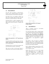
2.0 DESCRIPTION
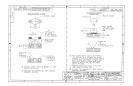
(Refer to installation drawing no. 103-1010-90
included as part of this manual.)
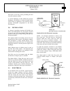
The 103A Series Sensors utilize a bimorph bender
crystal cantilevered from the side wall and attached to
the center of a thin recessed invar diaphragm.
Pressure acting on the surface of the diaphragm
results in a net force which strains (or deflects) the
diaphragm in proportion to the applied pressure. The
diaphragm bends the crystal creating an output
voltage which is also proportional to applied
pressure.
This voltage is fed to the gate of a miniature
MOSFET source follower amplifier which reduces
the output impedance to less than 100 Ohms allowing
the driving of long cables and permitting operating
directly into most readout instruments.
Refer to Bulletin G-0001B, “General Guide to ICP
®
Instrumentation” for a detailed description of the
built-in amplifier concept.
Models 103A, A02, A11, and A12 have output
signals superimposed upon a +4 V (approx.) bias
level at the amplifier output. All PCB signal
conditioners are designed to eliminate this bias
voltage while supplying power to the internal
amplifier.