


Drawing Number: 21082
Revision: NR
OPERATION MANUAL FOR
MICROPHONE
Series 103A
2
The result is a two-wire system, precluding the need
for multi-conductor cabling.
A second diaphragm, located behind the pressure
diaphragm and attached to another bimorph bender
crystal acting in opposition to the pressure crystal,
provides acceleration compensation to the Series
103A Sensors.
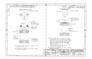
3.0 INSTALLATION
As shown in installation drawing 103-1010-90, the
Series 103A Microphones may be properly mounted
in several ways, the exact method chosen being a
function of the space available along with other use
dictated parameters.
The simplest method of mounting, and also the one
that utilizes the least volume, is the adhesive method.
The microphone is simply bonded directly to the
mounting surface with an (at least) .10” diameter hole
through the surface to feed the pressure signal to the
diaphragm.
Many different types of adhesives may be used to
bond the 103A in this manner. The important point
being to apply the adhesive very sparingly so that
removal does not damage the sensor.
The 103A may also be mounted using the Model
061A04 Servo clamps if space is available.
The Model 060A11 Clamp Nut may only be used
with the top connector Models 103A02 and 103A12
since the radial wire leads of the Model 103A and
103A11 would interfere with the clamp nut. The
installation drawing gives detailed instructions on
preparation of the port for this type of installation.
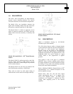
3.1 ELECTRICAL
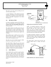
For the Models 103A and 103A11 (pigtail models),
connect the center conductor from the “Xducer”
output of any ICP
®
power unit to the white (Pwr/Sig)
lead and connect the outer shell of the “Xducer”
connector to the black (ground) lead. The black lead
is electrically connected to the outer case. (See figure
below.)
Models 103A & All: Electrical Connection
NOTE: No electrical connection is made to the
blue (vent) lead. This lead serves to vent internal
pressure within the sensor when the 103A and
103A11 are used in evacuated chambers. The
internal pressure bleeds out slowly around the wires
of this lead. This lead may be cut off flush with body
if the sensor will never be used in this manner.
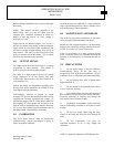
To make the electrical connection to the Models
103A02 and 103A12 (top connector models), simply
connect the “Xducer” output of the power unit to the
10-32 coaxial connector using a PCB Model 002C
Series coaxial cable.
The output signal is taken from the power unit
connector labeled “Scope” or “Output”. (See figure
below.)
1
2
3
4
MODEL 103A02 & A12
0
0
2
A
C
A
B
L
E
XDUCER
MODEL 482A04
P
O
W
E
R
U
N
I
T
SCOPE
TO
READOU
T
Models 103A02 & A12: Electrical Connection
WHITE
BLUE (N.C.)
XDUCER
BLACK
VIEW FROM
DIAPHRAGM
END
SCOPE
TO
READOUT
SERIES 480
B
A
T
T
E
R
Y
S
I
G
N
A
L
C
O
N
D
I
T
I
O
N
E
R