


Drawing Number: 21082
Revision: NR
OPERATION MANUAL FOR
MICROPHONE
Series 103A
3
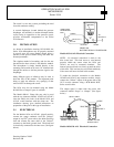
Refer to Guide G-0001B for tips on power and signal
utilization.
NOTE: The internal low-noise amplifier in the
Model 103A, A02, A11 and A12 differ from the
standard ICP
®
amplifiers described in Guide G-
0001B in that the turn-on (or bias) voltage is
nominally +4 volts.
Proper turn-on for Models 103A02, A11 and Al 2
will not give center scale reading on the fault monitor
meters found on most PCB signal conditioners but
will show a reading of approximately 20% of F.S. on
these meters. This puts it at the lower limit of the
green (or normal) area of the meters. This is normal
and in no way indicates faulty operation.
4.0 OUTPUT SIGNAL
The output signal from the 103A Series is a voltage
proportional to input pressure. The polarity is
positive-going for increasing input pressure.
The signal is of high enough level and low enough
output impedance to be fed directly into most
oscilloscopes, tape recorders, strip chart recorders, A
to D converters, etc.
Consult the factory for information regarding galvo
driving since special amplifiers are needed to drive
most high-current galvanometers.
Low-frequency response is limited by sensor
discharge TC (given in the specification sheet) and by
coupling time constants throughout the system. To
take full advantage of the TC of the sensor, make sure
that coupling TC's from power unit to readout are at
least an order of magnitude longer than the discharge
TC or use a direct-coupled signal conditioner such as
the Model 484B. Consult factory for details.
5.0 CALIBRATION
The 103A Series Sensors must be dynamically
calibrated using a known step function or pulse, or
with a microphone calibrator.
At PCB, the units are subjected to various calibrated
steps of pneumatic pressure to obtain a linearity curve
over the full range of the instruments.
6.0 MAINTENANCE AND REPAIR
The small size and sealed construction of the Series
103A precludes field maintenance and repair.
Should the time constant degrade or an abnormality
appear in the normal bias voltage, bake the unit out in
a +250° F oven for 1 to 2 hours, then re-test.
If this is not effective or if other problems should
occur, contact the factory for assistance in tracing the
problem or for instructions on returning the unit for
repair.
7.0 PRECAUTIONS
l.) Do not apply voltage to the unit without a
current-limiting device in the line such as
incorporated in all PCB signal conditioners, (20 mA
maximum) to do so will destroy the internal amplifier.
2.) Do not subject these units to temperatures
higher than 250° F.
3.) Do not attempt to disassemble these units as
to do so voids the warranty.
4.) Use caution when removing units that have
been mounted with epoxies or other strong adhesives.
Excessive squeezing or torquing may damage the
units and/or cause a calibration shift.
5.) In vibratory environments, secure cables and
leads to surrounding structures to avoid lead or cable
damage.
6.) Do not over torque when using the Servo
clamps or the clamp nut since this could damage the
units.
7.) Do not overpressure (see specs for
maximum pressure), to do so may change the
calibration.
®ICP is a registered trademark of PCB Piezotronics