


Installation Manual 19
Wiring
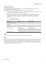
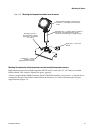
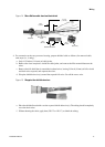
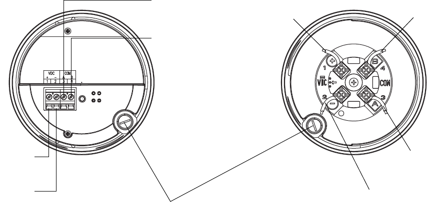
Figure 19 Connecting the wires at the core processor
7. Reinstall and tighten the core processor housing cover.
8. Additional wiring instructions for the transmitter can be found in the transmitter manual.
Note: Never ground the 4-wire cable shield and shield drain wire(s) at the transmitter.
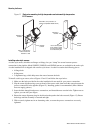
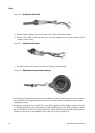
Junction box to a 9-wire remote transmitter or remote core processor
Follow the steps below to connect the 9-wire cable between the sensor and the transmitter or core processor.
1. Prepare and install the cable according to the instructions in Micro Motion’s 9-Wire Flowmeter Cable
Preparation and Installation Guide.
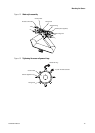
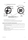
2. Insert the stripped ends of the individual wires into the terminal blocks. No bare wires should remain
exposed.
3. Match the wires color for color. For wiring at the transmitter or remote core processor, refer to the
transmitter documentation.
4. Tighten the screws to hold the wires in place.
5. Ensure integrity of gaskets, then tightly close and seal the junction box cover and all housing covers on
the transmitter or core processor.
Core processor housing internal ground screw
• For connections to earth ground (if core processor cannot be
grounded via sensor piping and local codes require ground
connections to be made internally)
• Do not connect shield drain wires to this terminal
Terminal 1
Power supply +
(Red wire)
Terminal 2
Power supply –
(Black wire)
Terminal 3
RS-485/A
(White wire)
Terminal 4
RS-485/B
(Green wire)
Standard core processorEnhanced core processor
Terminal 1
Power supply +
(Red wire)
Terminal 2
Power supply –
(Black wire)
Terminal 3
RS-485/A
(White wire)
Terminal 4
RS-485/B
(Green wire)