


5
Reference Manual
00809-0100-4952, Rev BA
Section 2: Installation
February 2014
Installation
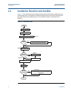
The following list is a summary of the steps required to complete a Pipe Clamp Sensor
installation.
1. Determine where the Pipe Clamp Sensor is to be placed within the piping system.
2. Establish the proper orientation as determined by the intended application.
3. Confirm the configuration.
4. Mount the sensor and tighten the clamp bolts.
5. Check the fit-up of the instrument assembly to the pipe.
6. Check for full contact between RTD sensor tip and pipe.
7. Wire the instrument.
8. Supply power to the transmitter.
9. Commission the instrument.
2.3 Mounting
2.3.1 Tools and supplies
Tools required include the following:
Open end or combination wrenches.
Adjustable wrench: 40mm (1½-in.) jaw.
Supplies required include the following:
Pipe compound or PTFE tape (where local piping codes allow).
2.4 Installation
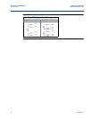
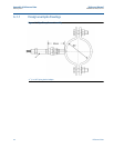
Step 1: determine the proper orientation
The Pipe Clamp Sensor should be mounted in a secure position to ensure there is no rotational
movement after installation. The mounting best practice is to install the sensor vertically.
Step 2: install the pipe clamp sensor
Mount the Pipe Clamp Sensor and tighten the bolts.
Step 3: install the transmitter
See appropriate transmitter product manual for sensor-transmitter installation.
Step 4: commission the transmitter
See appropriate transmitter product manual for transmitter commissioning instructions.