13-English
A
B
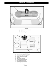
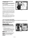
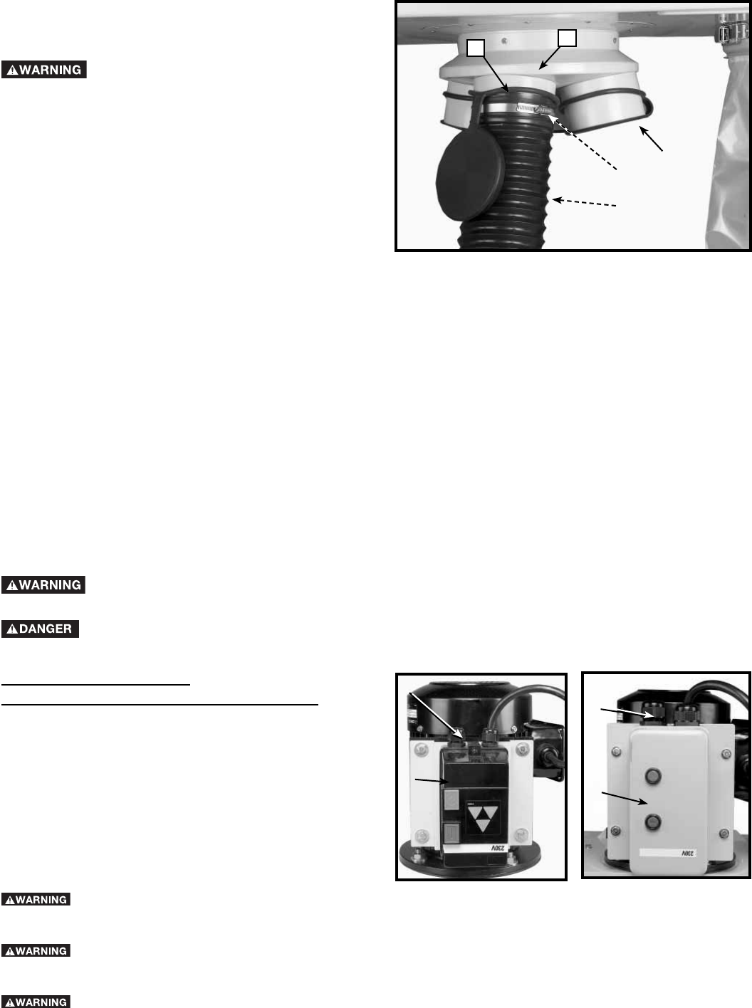
Fig. 13
A
B
C
D
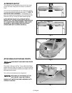
ATTACHING ACCESSORY HOSE
TO INTAKE PORT
DISCONNECT MACHINE FROM POWER
SOURCE BEFORE CONNECTING OR
DISCONNECTING HOSE .
Models 50-764/50-765 provides four 5” dust ports. Pro-
ceed as follows for each port with your accessory hos-
es.
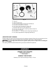
NOTE: Place open end (D) of intake cap rings around
and onto ends of each dust intake port before attaching
the hose.
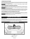
To assemble the 5” dust collection hose (not included)
to the motor and blower assembly, loosely attach hose
clamp (A) Fig. 13, around one end of flexible hose (B)
and assemble the hose to dust intake port (C). Tighten
hose clamp (A). Assemble the remaining clamp to the
other end of the flexible hose and to the woodworking
machine.
NOTE: See “ACCESORIES” section of this manual.
NOTE: Do not operate the dust collector with any of the
holes in dust intake port (C) Fig. 13 uncovered. To cover
a hole not being used by a hose, place the flat intake cap
(E) on dust intake port as shown in Fig. 13.
E
MODEL 50-764 THREE
PHASE INSTALLATION FOR 230 VOLTS
Your dust collector is supplied with a motor and a mag-
netic starter controller and must be permanently con-
nected to the building’s electrical system and grounded
to meet code.
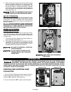
1. To connect the dust collector to a power system, re-
move controller cover (A) Fig. 14.
2. Bring three phase power line through the access
hole (B) Fig. 14, in the top of controller box and con-
nect the three power lines to terminals (C) Fig. 15,
and the green ground wire to ground screw (D).
BE SURE TO REINSTALL COVER BE-
FORE OPERATING.
DO NOT INSERT FINGERS OR ANY FOR-
EIGN OBJECT INTO THE DUST INTAKE PORT.
MAKE SURE UNIT IS PROPERLY
GROUNDED.
SINGLE AND THREE PHASE WIRING
INSTALLATION BY A QUALIFIED ELECTRICIAN IS RECOMMENDED TO ASSURE SAFE AND PROP-
ER WIRING AND PRODUCT OPERATION.
DISCONNECT POWER AT SOURCE BE-
FORE WIRING THE MACHINE.
Fig. 14
A
B
Model 50-765
Model 50-764


