


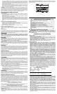

FIG. 1
FIG. 9
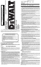
• The label on your tool may include the following symbols. The symbols and their definitions
are as follows:
V ......................volts A ................amperes
Hz ....................hertz W ...............watts
min ..................minutes
.............alternating current
...............direct current
n
o ..............no load speed
....................Class I Construction ...............earthing terminal
........................(grounded)
..............safety alert symbol
....................Class II Construction …/min ........revolutions or reciprocation
........................(double insulated) ...................per minute
BPM ................beats per minute
SAVE THESE INSTRUCTIONS
Motor
Your
D
E
WALT
tool is powered by a
D
E
WALT
-built motor. Be sure your power supply agrees
with the nameplate marking. Voltage decrease of more than 10% will cause loss of power and
overheating.
D
E
WALT
tools are factory tested; if this tool does not operate, check power supply.
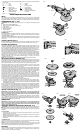
COMPONENTS (Fig. 1, 2, 3)
WARNING: Never modify the power tool or any part of it. Damage or personal injury could
result.
A. Speed Control Wheel (DW849 only)
B. Cushion Tool Reset (DW847, DW849 only)
C. Trigger Switch
D. Brush Inspection Cap
E. Spindle Lock Button
F. Auxiliary Handle
G. Trigger Locking Button
INTENDED USE
The DW845, DW847 and DW849 heavy-duty polishers are designed for professional use at
various work sites (i.e., construction sites). Do not use under humid conditions or in presence
of flammable liquids or gases.
The DW845, DW847 and DW849 heavy-duty polishers are professional power tools. Do not let
children come into contact with the tool. Supervision is required when inexperienced operators
use this tool.
Auxiliary Handle (Fig. 1)
An auxiliary handle (F) is furnished with your tool and can be installed on either side of the front
housing. This handle should be used at all times to maintain complete control of the tool.
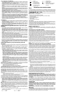
Variable Speed Switch
These tools are equipped with a variable speed switch that permits speed control from (0 to
1750 RPM - DW847) (0 to 1000/0 to 3000 RPM - DW849) (0 to 2300 RPM - DW845). To turn
the tool on, squeeze the trigger switch (C) shown in Figure 2 until the tool starts to run. The far-
ther you depress the trigger, the faster it will operate. Releasing the trigger turns the tool off.
Use lower speeds for applying liquid waxes and polishes and higher speeds for removing dried
liquid. Use the highest speed (fully depress trigger) for buffing the car to a final lustre.
The tool can be locked on for continuous use by squeezing the trigger switch fully and depress-
ing the lock button (G) shown in Figure 2. Hold the lock button in as you gently release the trig-
ger switch. The tool will continue to run. To turn the tool off from a locked on position, squeeze
and release the trigger switch once. Do not unplug the tool with the switch in the locked on
condition. Make sure the tool is not locked on when plugging in. A locked on tool will start
immediately when plugged in.
NOTE: The trigger can only be locked on with the tool running at the maximum RPM.
Speed Control Wheel (DW849 only)
The maximum speed of your tool can be changed by rotating the speed control wheel (A) to the
desired setting. The wheel incorporates detents to prevent inadvertent wheel movement and to
facilitate speed selection. For added versatility, the switch may be locked in its full on position
and tool speed changed by means of the speed control wheel (A) alone (see Figure 3).
The electronic speed control not only lets you select the speed to suit the job, but also helps
to maintain that speed as you load the tool by pressing down. It’s this feature, coupled with the
variable speed switch, that make this tool such a value.
The speed control wheel (A) can be set for any speed between 1000 and 3000 RPM and the
variable speed switch will then control tool speed from zero to the wheel setting. For example:
A control wheel setting of 2200 RPM will allow the variable speed switch to operate the tool
between zero and 2200 RPM, depending on how far the trigger is depressed. A wheel setting
of 1000 RPM would allow the switch to operate the tool from zero RPM to 1000 RPM.
The electronic speed control feature comes into play whenever the trigger switch is fully
depressed and the tool is running at the selected speed determined by the setting of the con-
trol wheel. As you load the tool by pushing it down on the work surface, (with the trigger fully
depressed) the electronic circuit inside the tool will compensate for the loading and maintain
the selected speed. If the speed selected by the control wheel is 2200 RPM, as in the example
above, the tool will maintain 2200 RPM, as it is loaded.
It is important to remember two things about electronic speed control:
1. The electronic speed control operates only when the trigger switch (C) is fully depressed.
2. The effect of electronic speed control is much easier to observe at lower speed settings
(2600 RPM and below), than at high speeds. As the tool approaches 3000 RPM, the effect
is considerably less dramatic.
Keep in mind that, with a conventional polisher running at a typical no load speed of 2400 RPM,
the tool slows down to about 2000 RPM under a polishing load. Your DW849 will continue to
run at 2400 RPM (or any speed you select with the control wheel) as a load is applied. Since it
doesn’t slow down, the speed may be greater than you’re used to so some extra caution should
be observed until you get the “feel” of your polisher. If you feel the speed is too great, you can,
of course slow the tool down with either the trigger switch or the control wheel.
Spindle Lock Button (Fig. 1)
WARNING: To reduce the risk of serious personal injury, turn tool off and disconnect
tool from power source before making any adjustments or removing/installing attach-
ments or accessories. Before reconnecting the tool, depress and release the trigger
switch to ensure that the tool is off.
In order to prevent the spindle of the tool from rotating while installing or removing accesso-
ries, a spindle lock button (E) has been provided in the gear head of the machine. To lock the
spindle, depress and hold the lock button. NEVER DEPRESS THE SPINDLE LOCK BUTTON
WITH THE TOOL RUNNING OR COASTING.
OPERATION
WARNING: To reduce the risk of serious personal injury, turn tool off and disconnect
tool from power source before making any adjustments or removing/installing attach-
ments or accessories. Before reconnecting the tool, depress and release the trigger
switch to ensure that the tool is off.
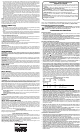
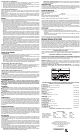
Attaching and Removing Polishing Pads (Fig. 4, 5)
WARNING: To reduce the risk of serious personal injury, do not allow any loose portion of
the polishing bonnet or its attachment strings to spin freely. Tuck away or trim any loose attach-
ment strings. Loose and spinning attachment strings can entangle your fingers or snag on the
workpiece.
TO ATTACH PAD
1. To attach pad (H), push the hub of the clamp washer through the hole in the center of the
polishing pad as far as it will go.
2. Engage the hexagonal hole in the backing pad. Holding the three pieces firmly together,
place the assembly on the tool spindle.
3. Hold the spindle lock button while turning the pads clockwise to thread them completely on
the spindle.
TO REMOVE PADS
Turn them by hand in the opposite direction from normal rotation to allow lock button to engage
spindle, then unscrew pads in normal direction for right hand thread.
NOTE: If you are using a polishing bonnet, rather than a pad, put clamp washer on first, pull
bonnet completely over backing pad and pull draw strings tight Tie bow knot and push knot and
all loose string completely under the inside, cloth edge of the polishing bonnet.
Polishing
These instructions and suggestions are intended to familiarize new operators in overall general
operation of power polishing. You will develop your own techniques which will make the job
easier and faster as you learn power polishing.
A
B
F
E
C
D
E
F
FIG. 3
A
FIG. 2
G
C
FIG. 4
H
I
J
K
FIG. 5
H
FIG. 6
J
L
M
I
FIG. 7
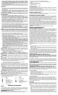
INSTALLING
INSTALLATION
NSTALACIÓN
E
FIG. 8
REMOVING
RETRAIT
QUITAR
E