


17
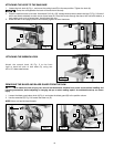
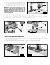
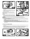
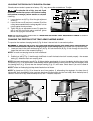
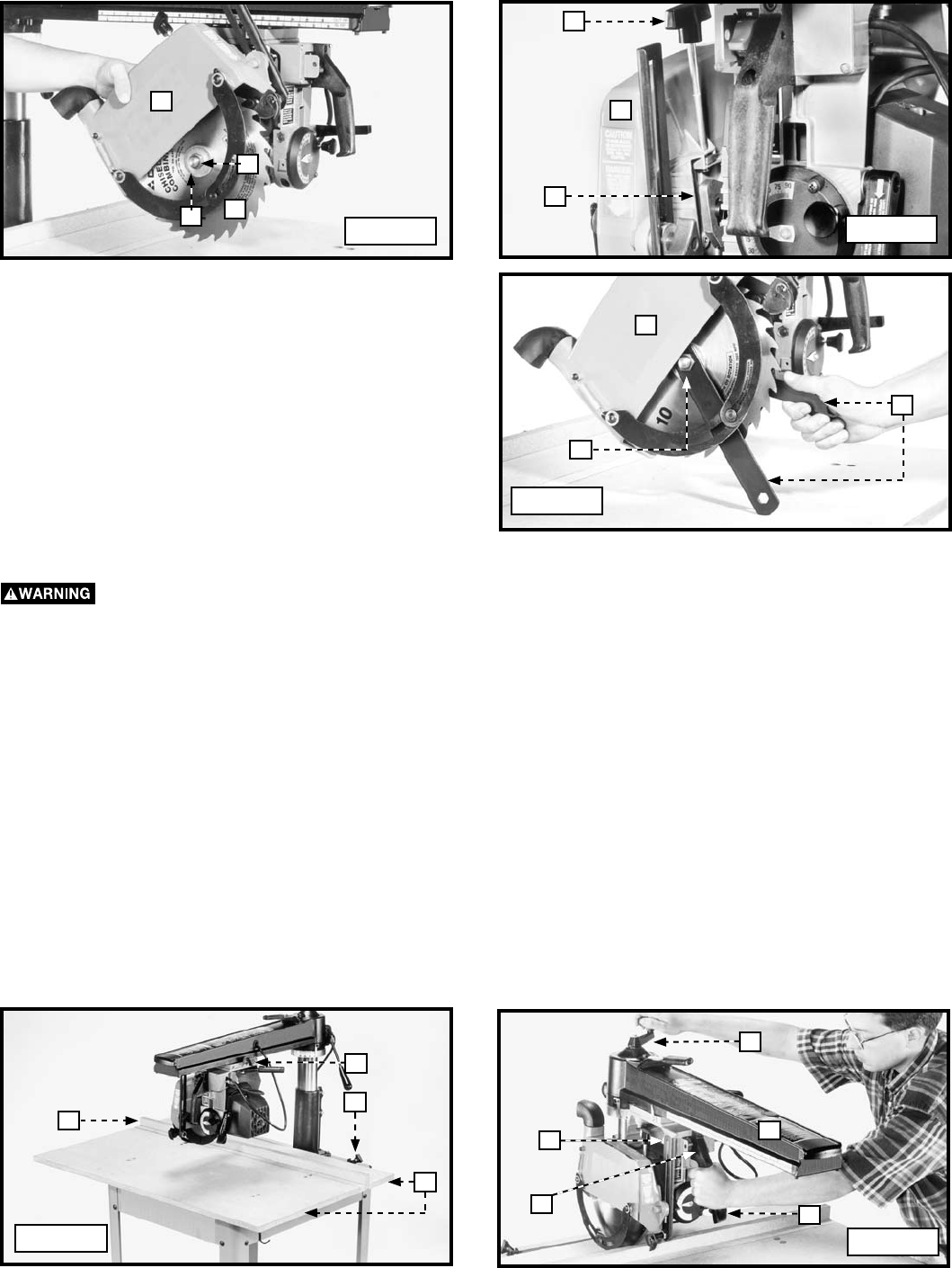
2. With the blade guard (B) Fig. 32 in the left hand, insert
the saw blade (C) into the blade guard (B) and on the
arbor shaft.
3. Atttach the outside (thin) blade flange (D) Fig. 36 to the
recessed side of the flange (D) facing in. Place the arbor
nut (E) on the arbor shaft.
NOTE: The arbor nut (E) Fig. 36 has a left-hand thread.
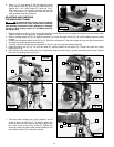
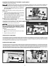
4. Lift the cam (F) Fig. 37. Attach the blade guard (B) to the
cuttinghead assembly.
NOTE: Seat the tongue of the guard in the groove of the
cuttinghead.
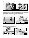
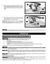
5. Pull back on blade guard (B) Fig. 38, so that it rotates to
the rear. Use the 7/8" box wrench around the arbor nut
(E), and the 7/8" open-end wrench on the flat of the arbor to hold it in place.
6. Rotate the blade guard (B) Fig. 38 to the horizontal position and tighten the clamp knob (H) Fig. 37.
Tighten the clamp knob (H) FIG. 37 and secure the blade guard before operating the machine.
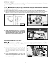
The lower retractable blade guard provides operator protection along the sides of the sawblade. To reduce the risk of
potential hazards, use the following rules:
A) KEEP YOUR HANDS AWAY FROM THE GUARD. As the blade cuts, the guard will lift and leave part of the blade
exposed.
B) SHUT OFF THE POWER BEFORE FREEING A JAMMED LOWER GUARD. The guard can get jammed in previous
kerfs in the table or fence. Always anticipate the path of the guard.
C) USE CAUTION when making bevel cuts to ensure that the lower guard is never pinched toward the blade.
D) THE LOWER GUARD CAN JAM AGAINST THE FENCE DURING NARROW IN-RIPS. Should the guard jam against
the fence, disconnect the saw from the power, wait for the blade to stop, then lift the blade guard and rest it on
top of the fence.
Fig. 36
E
B
D
C
F
B
H
G
E
B
Fig. 37
Fig. 38
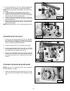
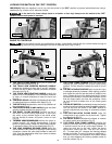
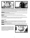
CUTTING INTO THE TABLE BOARDS
1. Attach the table boards (A) Fig. 38 and the fence (B). Secure the boards in place with table clamps, one of which is
shown at (C).
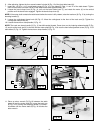
2. Return the cuttinghead (D) Fig. 39 to the rear of the track arm (E). Tighten the cuttinghead clamp knob (G) Fig. 37.
Check to see that the switch (H) Fig. 39 is in the “OFF” position and connect the saw to the power source.
3. While holding cuttinghead handle (L) Fig. 39 firmly, turn the switch (H) “ON”. Lower the track arm (E) by turning the
elevating handle (K). Lower the saw blade until it cuts into the table surface approximately 1/16” deep.
B
Fig. 39
G
Fig. 40
C
A
E
K
D
H
L