


19
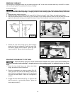
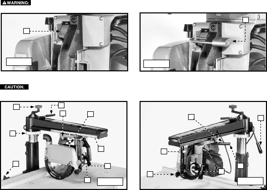
Fig. 43
A
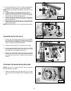
Fig. 44
D
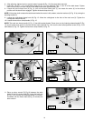
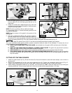
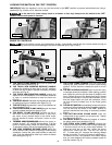
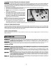
Study the following terms and explanations carefully to familiarize yourself with the controls before turning on
the power. Doing otherwise may cause damage to the saw or personal injury (Figs. E and F).
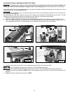
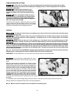
A. THE TABLE CLAMP KNOBS allow you to quickly set
the desired fence position (Fig. G).
B. THE TRACK ARM INDEXING RELEASE HANDLE
releases the indexing pin from the 0° and 45° positions
to allow the arm to rotate. Depress the handle to release
the index pin (Fig. G).
C. THE TRACK ARM ELEVATING HANDLE controls the
depth-of-cut in all operations. Turn the handle clockwise
to raise, or counter-clockwise to lower the track arm
(Fig. G).
D. THE MITER SCALE indicates the degrees left and right
for setting track arm to desired miter angle (Fig. G).
F. THE RIP SCALE indicates the in and out rip positions of
the cutterhead (Fig. E).
G. THE BLADE GUARD CLAMP KNOB clamps the blade
guard at rotated positions for ripping (Fig.G.
H. THE BEVEL CLAMP HANDLE controls the tilt of
the motor for bevel cutting operations. It also locks
the motor at any desired angle on the bevel scale.
Lift the handle to loosen, and push it down to lock
(Fig. G).
J. THE BEVEL INDEX RELEASE KNOB allows the motor to
position in the 0°, 45°, and 90° bevel settings. To tilt the
motor for bevel cutting, loosen the bevel clamp handle.
To release the index, pull out the release knob (Fig. G).
K. THE YOKE INDEXING RELEASE LEVER allows the
saw to achieve a 90° position for ripping or cross-cutting
operations. Loosen the yoke clamp handle to rotate the
yoke. Push the release lever either up or down to release
the indexing pin (Fig. G).
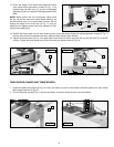
GUIDE TO CONTROLS
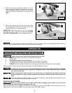
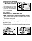
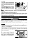
L. THE YOKE CLAMP HANDLE must be loose when
rotating the yoke between the rip and cross-cutting
position. Pull the handle to release and push it to lock
(Fig. H).
M. THE ANTI-KICKBACK DEVICE helps to prevent injury
or damage caused by kickback. When ripping, position
and clamp the yoke so that the blade is parallel to the
fence. Rotate the rear of the blade guard until it almost
touches the workpiece. Lower the anti-kickback rod so
that the fingers catch and hold the workpiece. Never
rip from the anti-kickback end of the blade guard
(Fig. H).
N. THE ON-OFF SWITCH is conveniently located, and can be
turned on or off in an instant for added operation protection.
You can also lock this switch in the "OFF" position to
prevent unauthorized use using an accessory padlock
(Fig. H).
P. THE CUTTING-HEAD CLAMP KNOB locks the
cutting-head at any position on the track arm. Tighten
the clamp knob (Fig. H).
R. THE BEVEL SCALE indicates the degree of rotation
for setting motor bevel positions (Fig. H).
S. THE TRACK ARM CLAMP HANDLE controls the
rotation of the track arm for all miter cutting operations.
It locks the track arm at any miter angle position. To
rotate the track arm to the right, loosen the clamp
handle and rotate the arm. The arm will stop at
45°. To rotate past 45°, depress the indexing release
handle and rotate. The arm will rotate an additional 5°.
To rotate to the left, the operation is the same except
that you must depress the indexing release handle to
start the rotation (Fig. H).
Fig. G
A
D
C
B
K
G
F
H
J
P
M
R
N
Fig. H
L
S
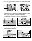
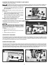
LOCKING THE SWITCH IN THE "OFF" POSITION
IMPORTANT: When the machine is not in use, lock the switch in the “OFF” position to prevent unauthorized use, using a
padlock (D) Fig. 44 with a 3/16" diameter shackle
In the event of a power outage (such as a breaker or fuse trip), always move the switch to the “OFF”
position until the main power is restored.