


– 8 – ETAsys.com
Specifications are subject to change without notice.
1601 Jack McKay Blvd. • Ennis, Texas 75119 U.S.A.
Telephone: 800-321-6699 • Fax: 800-996-3821
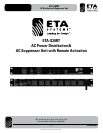
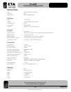
ETA-S20RT
AC Distribution & Suppressor Unit
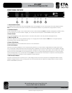
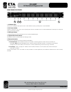
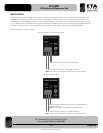
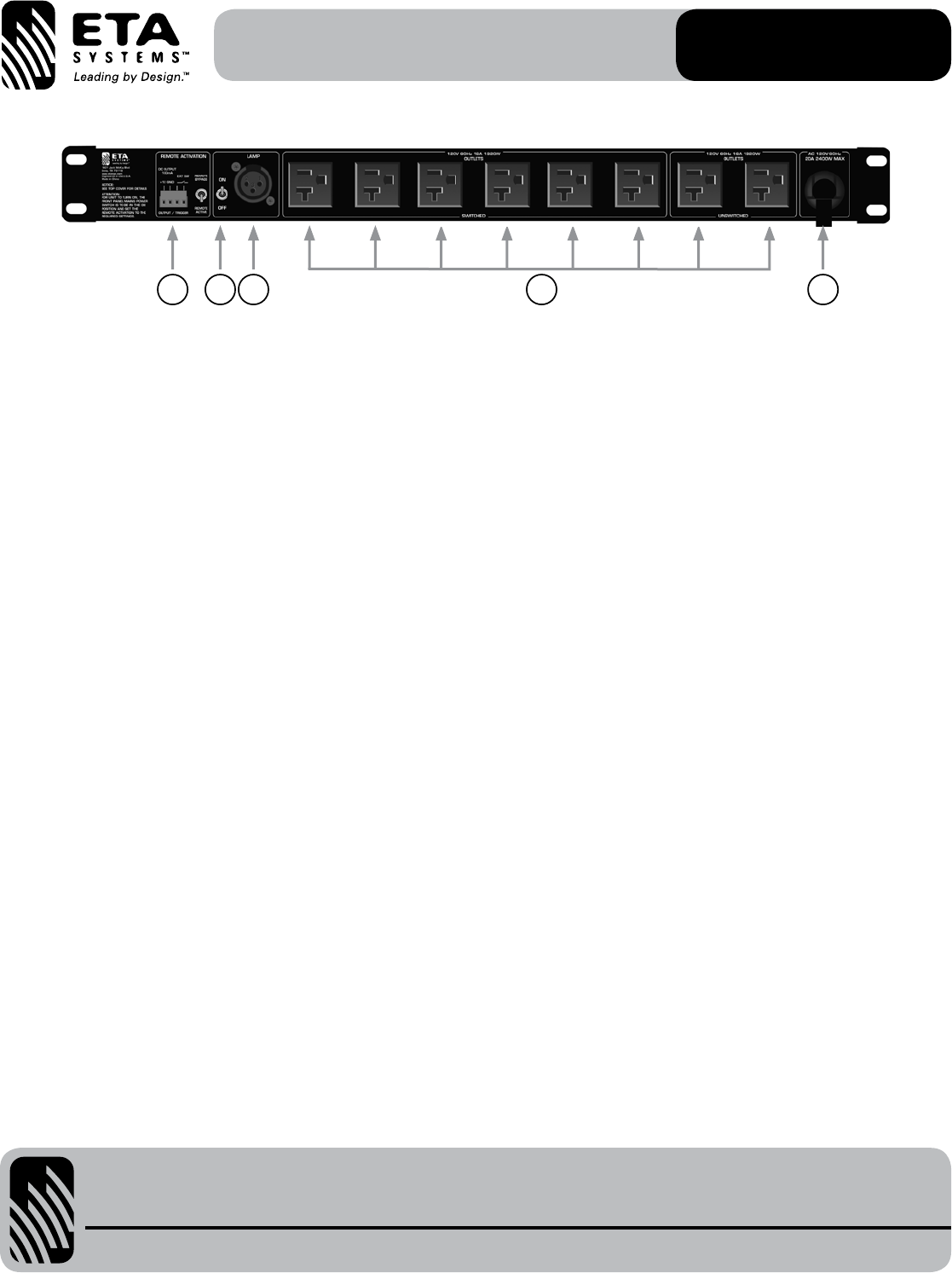
REAR PANEL FEATURES
1. AC Mains Input
Connectthe14Gauge9'(3m)powercordtoa20A120VACoutlettoprovidepowertotheETA-S20RT.
2. AC Power Outlets
These six outlets are “Live” when the front panel power switch is activated. The two Unswitched Outlets are always live if the power
cord is connected to 120VAC.
3. XLR Light Socket
A12VDCXLRlightsocketprovidespowerfortheoptionalAP-GNL18light.
4. Light Socket Power Switch
Two-positionswitchtopowerOn/OfftheXLRlightsocket.
5. Remote Activation
There are two methods to remotely activate the ETA-S20RT:
A. External Switch - The Ext SW terminals are connected to a latching type dry contact closure to activate the
ETA-S20RT. Note:TheRemoteBypassswitchmustbeshortedforRemoteActivation.Thisfeaturecanbeusedfor
Emergency Power Down (EPD), when tied into a normally closed latching contact closure (e.g. Fire Panel).
B. DC Voltage - When you apply 5V - 24VDC to the Ext SW terminals the unit will activate. See “Remote Activation
Drawings” for details.
Theterminalsmarked“+12V”and“GND”canbeconnectedtoaremotepanelLED(notincluded)toindicatefunctionwhenremotely
activated.
12345