


– 9 – ETAsys.com
Specifications are subject to change without notice.
1601 Jack McKay Blvd. • Ennis, Texas 75119 U.S.A.
Telephone: 800-321-6699 • Fax: 800-996-3821
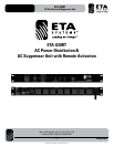
ETA-S20RT
AC Distribution & Suppressor Unit
INSTALLATION
Beforeinstalling,itisrecommendedtoreadtheentiremanualtoensureproperoperationandthatallfeaturesarebeingutilized.The
ETA-S20RT can be placed on a shelf or rack mounted in a standard 19" width rack. When rack mounted, placement within the rack is
exiblehowevertheETA-S20RTshouldbewithin6'ofadedicated20AACoutlet.Whenrackmounting,useRackRailtypescrewsof
10
⁄32" x 1". Always make sure the 20A outlet is properly inspected by a certified electrician prior to connecting the ETA-S20RT. Make sure
to inspect the equipment that will be connected to the ETA-S20RT to ensure it does not exceed 20A total amperage draw.
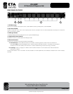
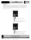
Remote Activation Connections Diagram
Remote Activation via Hard Contact Switch
Use External Key or Panel Switch, Hard Contact
ToRemotePanelLED,Usethe+12andGNDTerminals.
Note: Use a 2K ohm
1
⁄8W Resistor In Series with +12VDC and LED
Remote Voltage Activation
Apply+5V–24VDCandConnectaGroundtotheGNDTerminal
to Activate the Unit.
Note: It is OK to Have Two Wires In the Same Terminal.
ToRemotePanelLED,Usethe+12andGNDTerminals.
Note: Use a 2K ohm
1
⁄8W Resistor In Series with +12VDC and LED