


2
Trimming attachment KA-KS 120
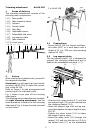
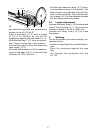
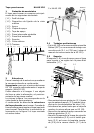
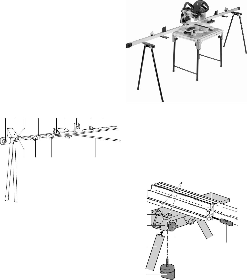
1 Scope of delivery
The trimming attachment consists of the
following main components:
(1.1) Stop profi le
(1.2) Tape measure clamp
(1.3) Support
(1.4) Support plate
(1.5) Stop fl ag
(1.6) Adjustable spacer
(1.7) Extendable end piece
(1.8) Leg support plate
(1.9) Tape measure
(1.13) Cross brace
1
1.9 1.7
1.12
1.131.11
1.6 1.4 1.31.8
1.10
1.5 1.2 1.1
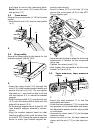
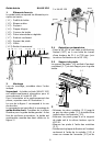
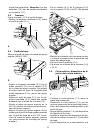
2 Set-up
When setting up the attachment, proceed in
the sequence specifi ed.
Important: you will require a crown mould-
ing stop (AB-KS 120) to make the connec-
tion to the KS 120.
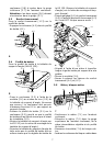
Refer to Figure 1 for the arrangement and
positioning of the individual parts.
Fig. 1 shows a rear view of the trimming
attachment.
The following section describes how to attach
the right trimming attachment. Use the
same procedure to attach the left trimming
attachment! Fig. 2 shows the stop mounted
on both sides!
2 x KA-KS 120
right
left
2.1 Preparations
– Secure the KS 120 to a Festool multifunc-
tion table (MFT) or a work bench with a
height of 31.1 in./790 mm (see operating
manual KS 120).
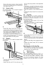
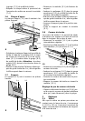
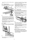
2.2 Leg support plate
The leg support plate (1.8) is designed to
support the trimming attachment and is
fi xed to the extendable end piece (1.7).
3
3.5
3.4
3.2
3.1
3.8
3.6 3.7
3.3
– Unscrew both rotary knobs (3.1) until the
two support legs (3.3) can be inserted into
the clamping sleeves (3.4).
– Insert the support legs until the leg sup-
port plate reaches the same height as your
KS 120.
– Tighten the rotary knobs (3.1) to clamp
the support legs in place.
– Screw the rotary knob (3.2) through the
recess (3.5) and into the slot nut (3.8) in
the bottom slot (3.7) on the extendable