


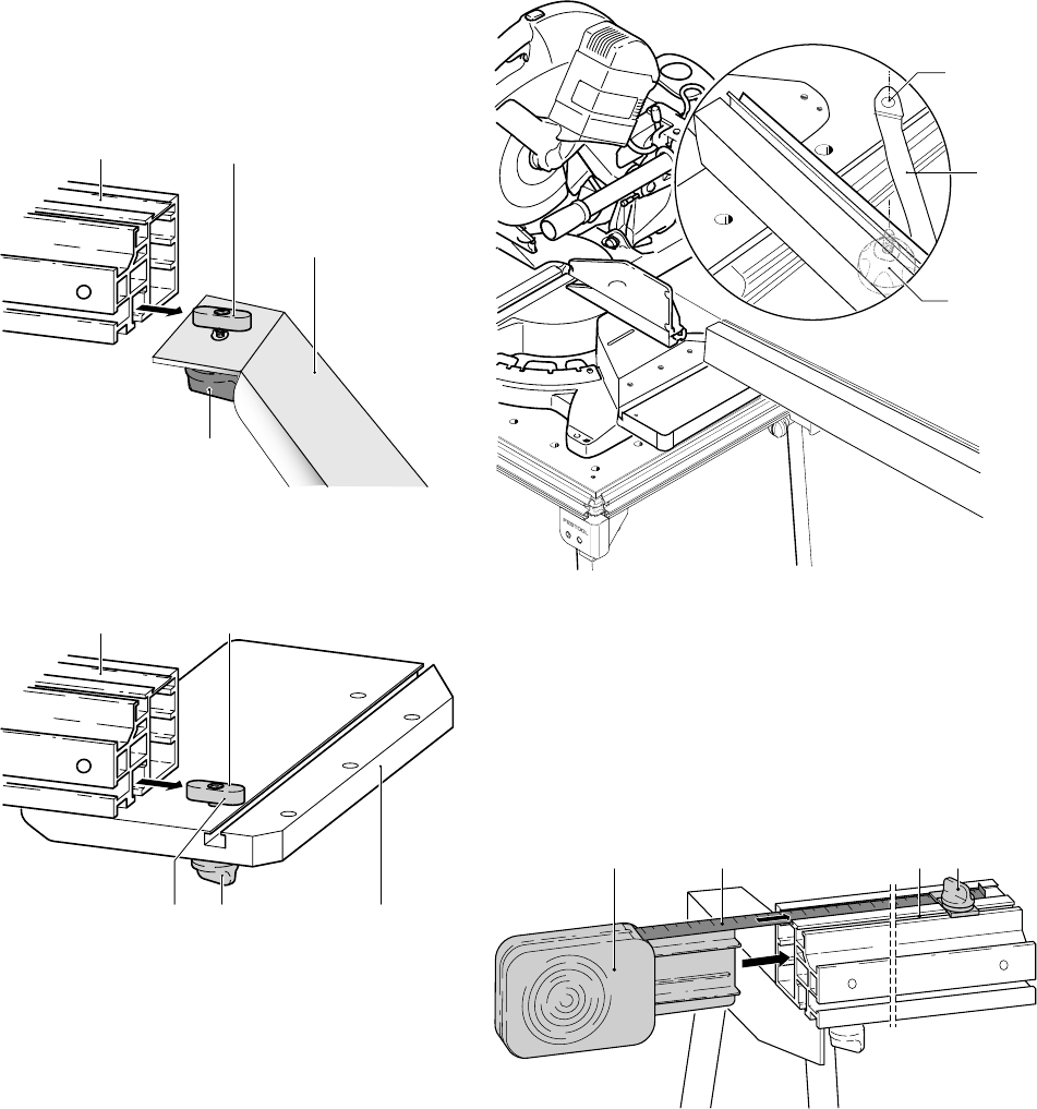
3
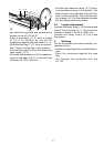
end piece to secure the mounting plate.
Note: The two cams (3.6) must slot into
the groove (3.7).
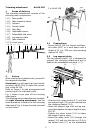
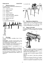
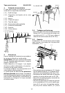
3.2 Cross brace
Secure the cross member (1.13) to the stop
profi le.
– Slide the slot nut (4.2) into the stop profi le
(4.1).
4
4.1
4.2
4.4
4.3
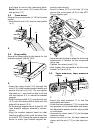
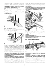
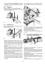
2.4 Stop profi le
Secure the stop profi le to the bench for the
bracket support (AB-KS 120):
5
5.4 5.35.5
5.1 5.2
– Insert the rotary knob (5.4) through the
hole (5.5) in the bracket support bench and
secure the slot nut (5.2). Do not tighten
the knob yet – you must be able to lift the
slot nut approx. 0.2 in. above the bracket
support.
– Slide the stop profi le (5.1) onto the slot nut
(5.2) until the stop profi le is fl ush with the
edge of the bench (5.3).
– Fit the bracket support bench to the KS 120
(see bracket support assembly instruc-
tions).
– Align the bracket support bench so that
the stop profi le is fl ush with the stop ruler
on the KS 120. Clamp the bracket support
bench in place (see bracket support as-
sembly instructions).
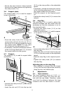
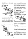
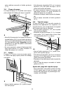
– Insert a clamp (6.3) in the hole (6.1) to
secure the cross brace (6.2) to the MFT.
Do not tighten yet!
6.1
6.2
6.3
6
–Use a long workpiece to align the trimming
attachment in relation to the compound
mitre saw.
– Tighten the rotary knob (5.4).
– Now tighten the connections on the cross
braces (4.4) and (6.3).
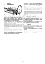
2.5 Tape measure, tape measure
clamp
7.2 7.3 7.47.1
7
– Insert the tape measure (7.1) into the
extendable end piece.
– Guide the tape measure (7.2) through the
top grooves on the extendable end piece,
the adjustable spacer and the stop profi le
in succession.
– Unscrew the rotary knob (7.4) for the tape
measure clamp.
– Insert the slot nut for the tape measure
clamp into the slot (7.3) on the stop pro-
fi le.