


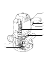

10
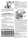
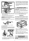
The parallel guide (accessory) can be used
for routing parallel to the edge of the work-
piece.
Secure both guide rods (9.2) with the two
rotary knobs (9.3) on the side stop.
Insert the guide rods into the grooves on
the router base to the required distance
and secure them by turning the rotary
knob (9.4).
Fine adjustment:
Unscrew the rotary knob (9.5) to make fi ne
adjustments with the adjusting wheel (9.7).
The scale ring (9.6) has a 0.1 mm scale
for this purpose. If the adjusting wheel is
held secure, the scale ring can be turned
separately and set to „Zero“. The millime-
tre scale (9.1) on the main casing is useful
when making larger adjustments. Tighten
the rotary knob (9.5) again on completion
of any fi ne adjustments.
Adjust both guidance jaws (9.8) so that
they are approx. 5 mm from the router. To
do this, undo screws (9.9) and tighten again
after completing the adjustments.
Slide the extractor hood (9.10) from behind
until it latches into place on the side stop.
You can connect an extractor hose with a
diameter of 27 mm or 36 mm to the extrac-
tor connector (9.11).
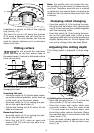
Routing with the FS
guide system
The guide system (accessory) facilitates rout-
ing straight grooves.
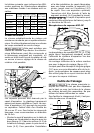
10.1
10.2
10.5
10.4
10.3
Fasten the guide stop (10.1) to the platen
with the guide rails of the parallel guide.
Fasten the guide rail with FSZ screw clamps
(10.3) to the workpiece. Make sure that
the safety distance X of 5 mm between the
–
–
–
–
–
–
–
front edge of the guide rail and cutter or
groove is observed.
Place the guide stop onto the guide rail as
shown in Fig. 10. To ensure a backlash-
free guidance of the router stop you can
adjust two guide cheeks with a screwdriver
through the side openings (10.2).
Screw the height-adjustable support (10.5)
of the router table’s threaded bore in such
a way that the underside of the router table
is parallel to the surface of the workpiece.
When working with marking-up lines, the
marks on the platen (10.4) and the scale on
the support (10.5) show the centre axis of
the cutter.
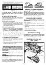
Fine adjustment
11.5
11.3
11.4
11.211.1
The distance X (fi g. 10) of the router to the
guide rail can be set fi nely using the fi ne ad-
justment (Accessories).
Fit the fi ne adjustment (11.5) between the
router and guide stop (11.4) on the guide
bars.
Insert the adjusting wheel (11.2) for the
fi ne adjustment in the recesses of the fi ne
adjustment and guide stop, and screw the
thread of the adjusting wheel approxi-
mately half way into the nut of the fi ne
adjustment.
To set, close the rotary knob (11.3) of the
fi ne adjustment and open the rotary knob
(11.1) of the guide stop.
After making the setting, close the rotary
knob (11.1) of the guide stop.
Copy cutting
A copying ring or the copying device is used to
exactly reproduce existing workpieces (both
available as accessories).
–
–
–
–
–
–