


8
5.1
5.2
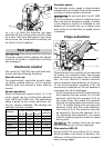
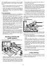
Installation is similar to that of the copying
ring (see fi g. 12).
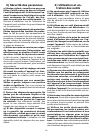
The hood can be cut off along the grooves
(5.2) using a hacksaw and can thus be re-
duced in size. The chip catcher can then be
used for interior radiuses up to a minimum
radius of 40 mm.
Milling cutters
Do not exceed the maximum
speed specifi ed on the tool and/or keep to
the speed range. Cracked or distorted cutters
must not be used.
6.1
6.2
6.3
A
B
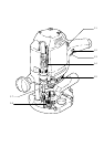
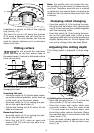
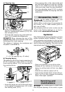
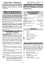
You can turn the machine upside down when
changing the tool.
Inserting the tool
Insert the router (6.3) into the open clamp-
ing collet as far as possible, but at least up
to the mark
on the router shank.
Press the switch (6.1) for locking the spin-
dle on the right-hand side (A).
Tighten the locking nut (6.2) with a 19 mm
open-end spanner.
Removing the tool
Press the switch (6.1) for locking the spin-
dle on the left-hand side (B).
Undo the nut (6.2) using an open-end
wrench (SW 19) until you are able to re-
move the tool.
–
–
–
–
–
Note: the spindle lock only blocks the mo-
tor spindle in one direction of rotation at any
one time. Therefore when the nut is undone
or tightened, the wrench does not need to be
offset but can be moved back and forth like
a ratchet.
Clamping collet changing
Press the switch (6.1) for locking the spin-
dle on the left-hand side. Fully unscrew the
nut (6.2) and remove from spindle together
with the clamping collet.
Press the switch (6.1) for locking the spin-
dle on the right-hand side. Insert a new
clamping collet with nut into the spindle and
slightly tighten the nut. Do not tighten the
nut until a milling cutter has been fi tted.
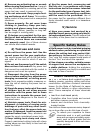
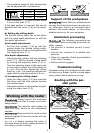
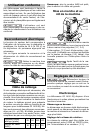
Adjusting the milling depth
The milling depth is adjusted in three stag-
es:
7.8
7.7
7.5
7.4
7.6
7.2
7.3
7.1
a) Setting the zero point
Open the clamping lever (7.7) so that the
stop cylinder (7.5) can move freely.
Place the router with router table onto
a smooth surface. Open the rotary knob
(7.4) and press the machine down until
the milling cutter rests on the base. Clamp
the machine tight in this position with the
rotary knob (7.4).
Press the stop cylinder against one of the
three sensing stops of the pivoted turret
stop (7.6).
–
–
–
–
–