


12 Domino XL DF700
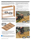
Using the Optional Cross Stops
The optional Cross Stops extend the position of the locat-
ing pins for wider tenon spacing. These are also adjustable
so the spacing can be tailored to the needs of the specic
application.
Note: The two Cross Stops are specic for right and
left-hand mounting, such that the locking levers point
toward the rear when locked. If you install the adjust-
able stop pins backward, the locking levers will point
forward when locked, and this will interfere with the
workpiece. If this happens, remove the stop pins from
the outrigger arms and turn them around.
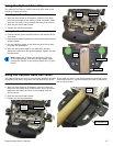
Setup
Mounting
Tab and Slot
Lock
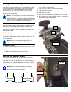
1. With the locking handle rotated toward the front of the
joiner (as shown in the upper photograph) insert the
mounting tab into the slot from below.
2. Turn the locking lever toward the rear to lock the Cross
Stop to the base of the joiner.
3. Loosen the clamping knob on the adjustable stop pin and
slide the pin to the desired position.
4. Before tightening the clamping knob, make sure both
pointers on the locating pin are pointing to the same
measurement on the outrigger arm.
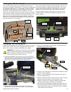
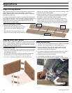
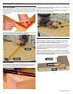
DF 500 versus DF 700 Setup
The new model Cross Stop is compatible with both DF 500
and DF 700 joiners by inverting the stop pin assembly. This
changes the height of the stop pins to line up with existing
mortises. (The previous model will still t the DF 700 joiner,
but the pins won’t line up with existing mortises.)
To invert the stop pin, loosen the clamping knob far enough
to allow the rear clamp to rotate, then rotate the rear clamp
180°, and retighten the clamping knob. The front of the
stop pin assembly indicates which position is for the respec-
tive joiner.
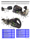
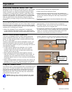
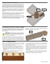
Calibration
To ensure that the stop pins are centered on either side of
the mortise location, they can be calibrated to the Domino
machine to which they are attached. If the stop pins are not
centered about the mortise location of the machine, loosen
the locking setscrew and rotate the eccentric adjuster
slightly. When the screw slot is vertical, the eccentric is in
the neutral position. When the screw slot is horizontal, the
eccentric is in the maximum offset toward or away from the
mortise position. (A stamped “0” indicates the minimum
offset of the eccentric.)
DF700
DF500
Eccentric
Adjuster
Locking
Setscrew
Clamping
Knob
Rear
Clamp
Stop Pin
Assembly
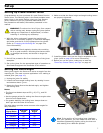
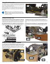
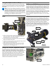
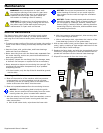
Using the Vertical Alignment Marks
The side of the fence body contains a pair of alignment
marks to indicate the vertical position of the mortising
location. These marks are helpful for identifying the mortise
location when plunging into the face of a large at work-
piece. Use these to align the joiner with a pencil line that
represents the desired center of the mortise location.
These can also be used in conjunction with the horizontal
alignment mark on the base of the joiner to position a
mortise at the intersection of two lines.
Alignment
Mark