


SYSTEM COMPONENTS
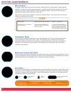
Wire Harness
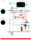
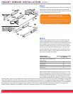
All necessary electrical wires and connectors have been included with this kit. Review Figure 1 before beginning
installation. You will have to put the major components in a position so that the wire harness will reach all of them.
Route the wire harness loosely throughout the vehicle as indicated in Figure 1. Each end of the wire harness is
marked with the major component that it will connect with.
Route the wire harness loosely throughout the vehicle as indicated in Figure 1, with the spine of the wire harness
installed on the right side of the vehicle.
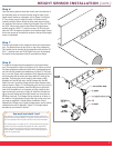
Compressor Relay
Select a location in the engine compartment to mount the compressor relay. This should be a protected location
to prevent damage from flying rocks, water or debris. The compressor relay is located on the wire harness,
simply pull the compressor relay off the wire harness for mounting. Ensure that a clear access to the electrical
connection on the compressor relay is maintained. Then plug the wire harness marked “relay” back into the
compressor relay connector.
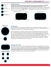
Electronic Control Unit (ECU)
The main electronic unit needs to be mounted in the interior of the vehicle, preferably under the dashboard. The wire
harness was designed to provide enough length so the ECU could be mounted under the dashboard and the harness
ran through the firewall to corresponding corners, valve block and power connections.
Valve Block
The valve block should be placed in a protected location to prevent damage from flying rocks or debris. Ensure that a
clear access to all of the fittings on the valve block is maintained. The valve block should be mounted with solenoids
pointing up or sideways, never pointing down. In order to ease installation, abbreviations for the correct plumbing
connections are scribed into the valve block.
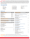
The valve block abbreviated connector notations are:
OD = outflow from dryer LF = left/front air spring PS = pressure sensor EX = exhaust
RF = right/front air spring ID = inflow to dryer LR = left/rear air spring Comp Inlet = compressor inlet
RR = right/rear air spring
2
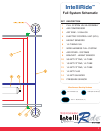
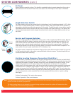
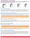
10-32 x 1-3/4” Socket Head
Cap Screw (2)
Silencer
(1)
Pressure
Sensor (1)
1/4” NPT Straight
Fittings (8)
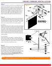
TIPS
1. Do not run the wire harness near vehi-
cle exhaust system.
2. Secure harness firmly to vehicle with
the provided tie wraps.
3. Make sure wire harness does not inter-
fere with any moving parts of the vehicle.
4. Start with the ECU connectors and
then begin running the harness into the
interior of the vehicle.
5. Many vehicles have a blank hole in the
firewall to run wires through.
6. A grommet has been provided if a 1”
hole must be cut to get the wire harness
to the interior. Before drilling the holes,
make sure all electrical, brake and fuel
lines are cleared from the path of the drill.