


SYSTEM COMPONENTS (cont.)
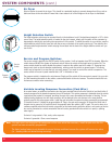
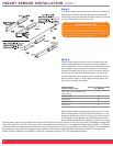
Air Dryer
Select a location to mount the air dryer. This should be a protected location to prevent damage from flying rocks or
debris and close to the valve block. Ensure that a clear access to all of the fittings on the air dryer is maintained.
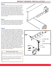
Height Selection Switch
The height selection switch may be mounted directly in the dashboard, only if the dashboard material is 1/8” in thick-
ness or less. The height selection switch is located on the wire harness, simply pull the switch off the connector by
depressing the locking clip and pulling the connector off of the switch. To mount the switch to your vehicle, snap the
height selection switch into the open hole with the arrows on the back of the switch pointing up. Then take the wire
harness marked height selection switch and plug the end back into the back of the height selection switch until you
hear it click.
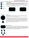
Service and Program Switches
The service switch is basically the ON/OFF switch for the system. It will not operate when RED is showing. When the
switch shows all BLACK the system is functional and will return the vehicle to the height prior to ignition off. The
service switch should be used to disable the system if repairs to the vehicle need to be made. I.E. changing tires,
damper work (such as shock absorber replacements), working under the vehicle or general repairs. The service
switch may be mounted in an area that you can easily access if you need to work on the vehicle’s suspension. The
service switch will mount in panel material that is 1/8” in thickness or less.
The program switch is located on the wire harness. Simply pull the switch off the connector to mount it to your vehi-
cle. After mounting the switch to the vehicle, reconnect the switch to the wire harness. The switch should click into
the harness connector when connecting.
Variable Leveling Response Connection (Park Wire)
As an extra feature, an additional connection wire has been provided that will allow the vehicle to level itself within 5
seconds compared to the standard response time of 40 seconds. This quicker response is desirable when the vehicle
is parked and the payload is increased, providing the user with a more immediate confirmation of leveling. The tan
variable-leveling-response wire with clear connector will be attached to the wire harness in the same location
originally used for the red program switch. Install the park wire after the system has been successfully programmed.
To connect the wire:
1. Unplug the program button. 2. Plug in the park wire connector. 3. Connect the other end of
the park wire to ground or to a switch that will be grounded when the vehicle is NOT in park. This can be done via a
customer supplied switch that will switch out ground for the faster leveling while the vehicle is not moving or the tan
wire can be connected to a vehicle wire/switch that will not be grounded while the vehicle is in park (i.e. parking
brake signal).
Park wire if not grounded = Fast, overly active response
Park wire if grounded = Slow, normal response
Note: If the park wire is not connected, the compressor will be more active than necessary. Install the park wire after the
system has been successfully programmed.
The faster leveling feature is not desirable for normal driving conditions because the system will become too active,
(i.e. - leveling when not desired during cornering).
4
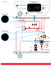
Service
Switch
Program
Switch