


SYSTEM COMPONENTS (cont.)
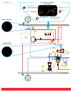
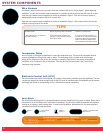
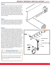
Height Sensors
The height sensor connections must go to their corresponding corners for proper sensor operation. THE HEIGHT
SENSORS AND THE WIRE HARNESS CONNECTIONS ARE LOCATION AND POSITION SENSITIVE. The sensor
connectors are laid out so they work with the sensors mounted on the outside of the frame rail, with the arms pointed
toward the rear of the vehicle. If the height sensors are mounted inside of the frame rail, the arms must point toward
the front of the vehicle. The system WILL NOT work if the height sensors are mounted incorrectly or if the wire
harness connector is in the wrong corner.
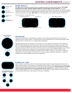
Compressor
Select a convenient location for mounting the compressor. This location should provide ample air flow and be
protected from most airborne debris. The surface should be rigid to support the unit. Some examples might include
under the hood on a fender well, or in a vented storage compartment.
Using the compressor feet as a template, mark the three 3/16” holes. Remove the compressor and drill the three
3/16” holes. Before drilling the holes make sure all electrical, brake and fuel lines are cleared from the path of the
drill. It is recommended that burrs be removed from the holes so as not to damage the rubber isolator. Mount the
compressor using the 10-32 machine screws, 10-32 nylon lock nuts and 3/16” flat washers located in your hardware
pack. Proper mounting of this compressor will provide maximum isolation. DO NOT OVER TIGHTEN, further
tightening will crush the insert and isolator and reduce vibration isolation. Secure the ring terminal to a grounded
component of the vehicle’s chassis. Find the red wire on your wire harness marked air compressor. Connect the
wiring harness to the female spade terminal on the compressor.
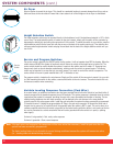
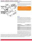
3-Gallon Air Tank
Select a location to mount the air tank. This should be a protected location to prevent damage from flying rocks or
debris. Using the holes in the tank brackets as a template, mark the locations of the mounting holes on the mounting
surface. Use a center punch to mark the center of the holes on the mounting surface.
Before drilling the holes make
sure all electrical, brake and fuel lines are cleared from the path of the drill
. Drill four 3/8” holes on the center
marks. Using the supplied 3/8”-16 x 1” hex bolts and 3/8”-16 nuts and 3/8” washers, attach the air tank to the vehi-
cle. Ensure that a clear access to the fittings on the air tank is maintained.
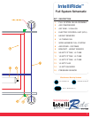
3
Shown with mounts
and air filter.
1/8 NPT Fitting (1)
3/8”-16 x 1 Hex
Head Bolt (4)
3/8”-16 Flat
Washer (4)
3/8”-16 Flange
Lock Nut (4)
1/4 NPT
Fitting (1)
1/4 NPT
Plug (1)
Air Tank Mounting Hardware
M5 Nylon Lock
Nut (8)
M5 x 8mm
Machine Screw (8)
M6 Nylon Lock
Nut (4)
M6 X 16mm
Machine Screw (4)
Axle Mounting Bracket (4)
Hose Clamp (4)
Height Control Linkage (8)
Height Control Arm (4)
Height Sensor Template (4)
Height Sensor Bracket (4) Height Sensor (4)