


11
Operation
1. The pressure in the tank is controlled by the action of
the pressure switch. When the set maximum pressure
is reached the pressure switch activates and the motor
is switched off. The pressure then decreases as the
air is used by the connected tool until the set minimum
pressure is reached after which the pressure switch
causes the motor to switch on again. The operator of
the compressor should be well aware that during use of
the compressor the motor will start and stop under the
influence of the rising or falling pressure in the tank. The
motor will start without any warning.
2. The maximum and minimum pressures are factory set
and the operator should not try to change them.
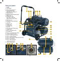
3. All accessories are connected to either the Nitto style
quick coupler regulated air
outlets (4) or the removable
tank inflator hose (27).
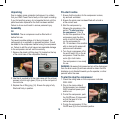
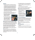
4. The pressure of the regulated
quick connect outlets is shown
on the regulated outlet pressure
gauge (6). The regulated
pressure can be adjusted by
turning the regulating knob (5).
Note. To obtain the correct output reading on the regulated
output gauge, the air must be flowing through the outlet(s)
(4). The regulating valve should be adjusted and the gauge
read with the outlet valve open and the air being discharged
from the regulated outlet through the accessory being
used. If you are using both of the regulated outlets (4)
simultaneously make sure that the tools being connected
have the same pressure operation requirements. To
increase the air pressure, rotate the regulating valve
clockwise. To decrease the pressure, rotate the regulating
valve anti-clockwise.
Note. If you do not allow the air to discharge while you
are setting the regulator, the pressure as indicated on the
regulated outlet gauge will be incorrect. This gauge ONLY
indicates the correct pressure while air is being discharged
from the outlet.
5. On completion of the task, i.e. when you have finished
using the compressor, or when you are leaving the
compressor unattended, turn off the compressor in the
following way:
• Lift the on/off switch (2) to the off position
• Wait for the pressurised air to bleed from the release valve.
Note. You will hear a short air discharge of approx
½ second however, this discharge only occurs if the
compressor is actually running at the time, and not in idle.
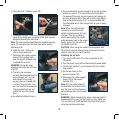
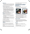
• Switch off the electrical
power supply and remove the
electrical plug.
• Pull the ring on both of the
safety valves (7) to ensure all
the pressurised air is released
from the tank, or open the both
drain cocks (9) to release the
pressure from the tank.
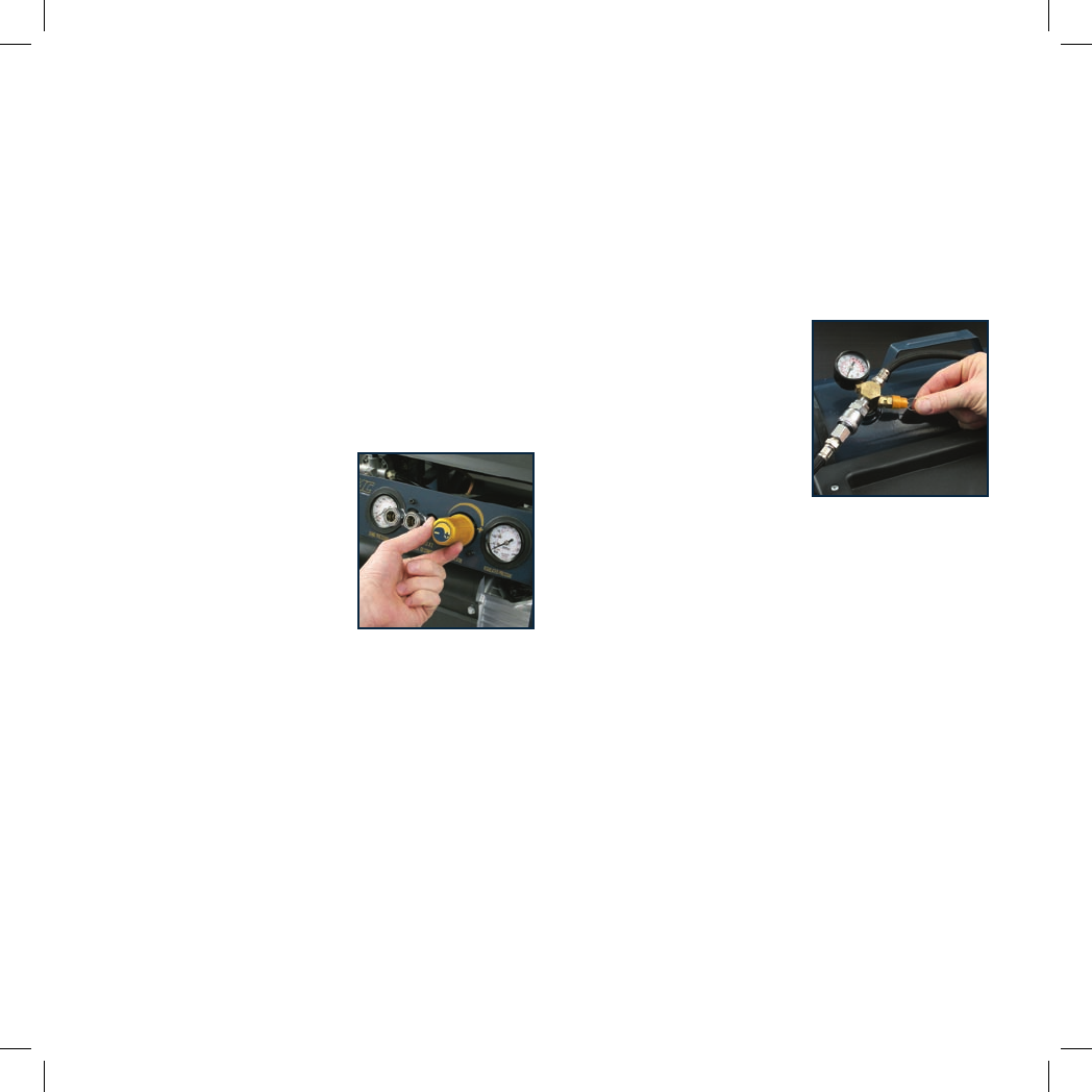
Tank removal/installation
This twin tank air compressor has the added benefit of a
removable tank which provides a mobile source of limited/
short term compressed air. This has many advantages
including inflating flat tyres on site as well as performing
small brad nailing tasks.
Note. It is important that end users understand the
capabilities of the removable tank and work with in it’s
capabilities.
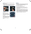
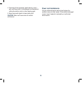
Removing the air tank:
1. Turn the On/Off switch (2) on the compressor to the
off position.
2. Turn the power supply off and disconnect the power cable.
3. Lift the main handle (1) up and away from the portable tank.