


10
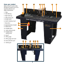
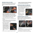
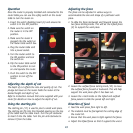
Attaching the fence to the table
The rear fence (7) is slideable and attaches to the table
through the two channel openings on the table. The
infeed (9) and outfeed (10) fence attach to the rear
fence.
1. Using a small carriage bolt, washer and large knob
attach the adjustable fence bracket (8) to the left
hand side of the rear fence (7). Feed the carriage bolt
through the bottom of the rear fence and through the
slot in the adjustable fence bracket. Place a washer
over the bolt and secure using a large knob.
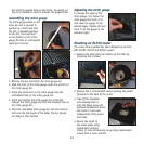
2. Position the router table so you are facing the rear of
the table.
3. Align the rear fence (7) over the channel openings in
the table. The large dust extraction port in the fence
should face the rear of the table.
4. Feed the long carriage bolt
from the bottom of the
table and insert it through
the channel opening in
the table and through the
hole on the right side of
the fence and through the
adjustable fence bracket.
Secure the bolt with a flat
washer and a large lock
knob.
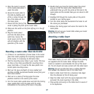
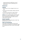
5. Feed the medium carriage bolt through the channel
opening on the left side of the table and through the
opening on the left side of the fence. Secure the bolt
with a flat washer and a large lock knob.
Attaching the infeed and outfeed fence
1. Place one sliding panel along the front side of the
fence and align the channel openings on the panel
with the holes along the front of the fence.
2. Place a small carriage bolt
through each of the two
openings on the front of
the panel and secure each
bolt with a flat washer
followed by a small lock
knob.
3. Repeat steps 1 and 2 to
secure the second sliding
panel to the fence.
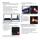
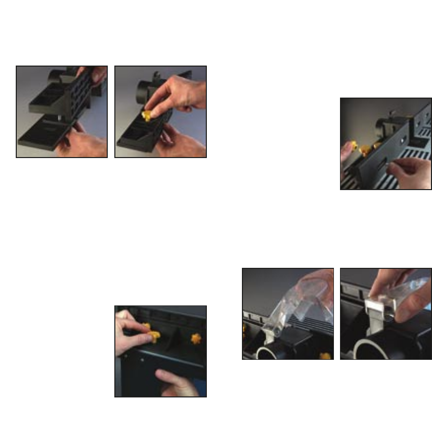
Attaching the guard to the fence
The guard (13) protects the operator from the cutting
edge of the router bit. A pin secures the guard to a
support on the fence. The guard will move freely when it
is attached properly to the fence.
1. Place the arm of the guard (13) over the support base
on the fence (7).
2. Align the openings on each side of the guard arm with
the openings on the support base on the fence.
3. Slide the guard pin through both sides of the guard