


9
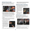
Attaching the legs
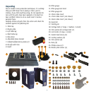
1. Place the table (1) upside down on a flat surface. The
hole and slots in the table should be furthest away
from you.
2. Position the left table leg (2) on the right hand
side and secure to the table using 4 screws, locking
washers, flat washers and nuts.
3. Position the right table leg (3) on the left hand
side and secure to the table using 4 screws, locking
washers, flat washers and nuts.
4. Turn the table over and set it on its legs.
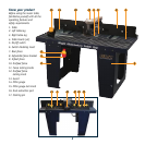
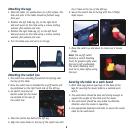
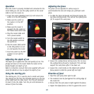
Attaching the switch box
1. The switch box assembly fits behind the left leg near
the top of the table.
2. Once the switch box is installed the on/off switch will
be positioned on the right hand side of the left leg.
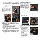
3. An electric cord and an
electric outlet for the router
are located at the rear of
the switch box.
4. Place the switch box behind the left leg.
5. Align the screw holes on the top of the switch box with
the 2 holes at the top of the left leg.
6. Secure the switch box to the leg with the 2 Philips
head screws.
7. Move the switch up and down to make sure it moves
freely.
Note. The on/off switch
features a switch disabling
insert for greater safety when
the tool is left unattended.
The switch disabling insert
must be in place before using
the tool.
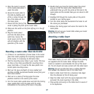
Securing the table to a work bench
1. Both table legs feature openings at the base of the
legs for securing the router table to a suitable work
bench.
2. The work bench should be level and strong enough to
support the weight of the table and the router.
3. The work bench should be very stable to eliminate
vibration when the router is operating.
4. Use appropriate fasteners and bolts to secure the router
table to the work bench.