9
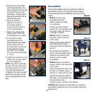
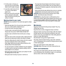
2. Allow the depth gauge (4) to
make contact with the turret stop
(8).
3. Loosen the depth lock lever (7)
and lower the machine body until
the router bit just touches the flat
surface. Tighten the depth lock
lever to maintain the position
of the bit just touching the flat
surface.
4. Take note of the measurement on the depth label.
5. Raise the depth gauge (4) and tighten using the depth gauge
locking knob (5). The difference in distance between the new
measurement and the original measurement will be equivalent
to the depth of cut. Use the depth adjustment (6) to set the
cutting depth. The micrometer depth adjustment (20) can be
used for precision setting. One complete turn of the micrometer
depth adjustment represents 1mm.
6. Loosen the depth lock lever (7) and raise the machine body.
7. When making a subsequent cutting operation, the final depth of
cut will be reached when the depth gauge (4) touches the turret
stop (8).
8. The depth turret stop (8) has
eight steps. By rotating the depth
turret stop it is possible to quickly
and easily set the depth at eight
different levels. This procedure is
particularly useful when you wish
to make a deep cut in a number
of stages.
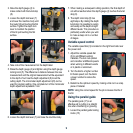
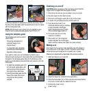
Variable speed control
The variable speed dial (3) is located on the right hand side near
the power cord.
1. Adjust the variable speed dial
(3) to suit different working
materials. The tool cuts quicker
and smoother at different speeds
when working in different woods
or in plastic or aluminium.
2. Turn the dial to a higher number
for faster speed, turn the dial to
a lower number to reduce the
speed.
3. Determine the optimum speed by making a trial cut in a scrap
piece of material.
NOTE. Using the correct speed for the job increases the life of
the bit.
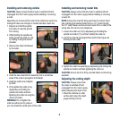
Using the parallel guide
The parallel guide (17) is an
effective aid to cutting in a straight
line when chamfering or grooving.
1. Loosen the parallel guide locking
knobs (15).
2
3 3
5
5
8
1
1