


10
To start the air compressor
1. Check the rating label on the compressor
indicates 230V-240V.
2. Make sure that the selected location for the compressor
is clean, dry, well ventilated and without any obstruction.
3. Conduct a visual check to the make sure that compressor
is not damaged and is fully in tack.
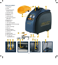
4. Make sure that he drain cock (13) is installed and
screwed into the closed position.
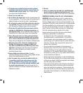
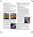
5. Connect the air hose to the quick coupler located on the
air compressor, by pushing back the outer sleeve of the
quick coupler (Fig. A) and inserting the end of the hose.
Release the outer sleeve and make sure the hose stays
in place (Fig. B).
6. Install the desired air accessory into the quick coupler at
the end of air hose by pulling back on the outer sleeve
of the quick coupler and inserting the accessory into it.
Release the outer sleeve and make sure the accessory
and hose are securely connected. For instructions on
how to assemble the accessories refer to pages 11 and 12.
7. Plug in the mains cable of
the compressor to a standard
240V household power point
and turn it on.
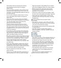
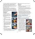
8. To start the compressor, press
the yellow “On/Off” (1) switch
to the “on” setting located on
top of the compressor (Fig. C).
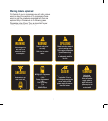
WARNING. Be aware that pressurised air will be discharged
from the outlet and care should be taken that this discharge
is not directed towards you the operator, or other persons
within the area.
9. To stop the compressor, push the yellow “On/Off” (1)
switch to the “off” setting.
Operating the air compressor
1. The pressure in the tank is controlled by the action of
a pressure switch. When the set maximum pressure is
reached the pressure switch activates and the motor
is switched off. The pressure then decreases as the
air is used by the connected tool until the set minimum
pressure is reached after which the pressure switch
causes the motor to switch on again. The operator of
the compressor should be well aware that during use of
the compressor the motor will start and stop under the
influence of the rising or falling pressure in the tank. The
motor will start without any warning.
2. The maximum and minimum pressures are factory set
and the operator should not try to change them.
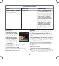
3. All accessories are connected
to the regulated outlet valve (8).
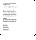
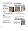
4. The pressure of the regulated
outlet, as shown on the
regulated outlet pressure
gauge (12), can be changed
by turning the regulating
knob (9) (Fig. D).
Note. To obtain the correct output reading on the regulated
output gauge, the air must be flowing through the regulated
outlet valve and the selected air tool/accessory.
The air pressure regulating knob should be adjusted
and the gauge must be read. Only read the gauge when
the regulated outlet valve has the air hose connected
with the selected air tool/accessory attached and drawing
air/discharging.
Do not start the application until you have set the regulated
outlet pressure accordingly for the selected tool/accessory.
A B
C
D