


10
the adjustable fence bracket.
Secure the bolt with a flat
washer and a large lock knob
(fig. G).
4. Feed the medium carriage bolt
through the channel opening
on the left side of the table and
through the opening on the left
side of the fence. Secure the
bolt with a flat washer and a large lock knob.
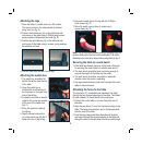
Attaching the infeed and outfeed fence
1. Place one sliding panel along
the front side of the fence and
align the channel openings on
the panel with the holes along
the front of the fence.
2. Place a small carriage bolt
through each of the two
openings on the front of the
panel and secure each bolt
with a flat washer followed by a small lock knob (fig. H).
3. Repeat steps 1 and 2 to secure the second sliding panel
to the fence.
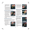
Attaching the guard to the fence
The guard (13) protects the operator from the cutting edge
of the router bit. A pin secures the guard to a support on
the fence. The guard will move freely when it is attached
properly to the fence.
1. Place the arm of the guard
(13) over the support base on
the fence (7) (fig. I).
2. Align the openings on each
side of the guard arm with the
openings on the support base
on the fence.
3. Slide the guard pin through
both sides of the guard arm
and the support base on the
fence (fig. J). Tap gently on
the pin if needed to insert it
through the support base.
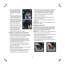
Adjusting the mitre gauge
1. Place the mitre gauge bar into
the channel that runs
the full length of the table.
The bar should run freely
in this channel (fig. K).
2. To change the angle of the
mitre gauge (14) loosen the
mitre gauge lock knob (15)
and move the gauge to the
desired angle.
3. Tighten the lock knob to set the gauge at the selected angle.
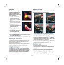
Mounting an R1200 router
The router plate supplied has
been designed to suit the
GMC R1200, R1250, R2050,
MAG1500R and MAG2050R
routers.
1. If the router plate is attached
to the table remove it by
loosening the 4 screws (fig. L).
2. Secure the router to the router
plate using 3 x M6 countersink
cross head screws (1 x 12mm
(for the blind hole), 2 x 16mm)
(fig. M).
3. Once the router is secured to
the router plate place it under
the table.
H
J
I
K
G
L
M