


10 309942
Pressure Control Repair
Motor Control Board
Removal
1.
Relieve pressure; page 5.
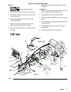
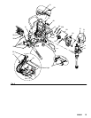
2. Fig. 3. Remove four screws (38) and cover (96).
3. Disconnect display connector (A) from motor
control board (95).
4. Remove bottom two screws (39) and allow control
panel (68) to hang down freely.
5. Disconnect control board power lead(s) (D) from
ON/OFF switch (33) and motor control board (95).
6. Disconnect potentiometer connector (C) from
motor control board.
7. Disconnect 15/20A switch (178) (1595).
8. Disconnect transducer connector (E) from motor
control board.
9. Disconnect motor connectors (F, G and H) from
motor control board.
10. Remove top two screws (39) and control box (61).
11. Remove five screws (27), three screws (102) and
motor control board.
Installation
1. Fig. 3. Apply small amount of thermal compound
110009 (5) to shaded component areas on rear of
motor control board (95).
CAUTION
To reduce risk of motor control board failure, do not
overtighten screws (102) which can damage the
electric components.
2. Install motor control board (95) with five screws
(27). Torque to 10–12 in-lb (1.13 – 1.35 N·m).
Install and torque three screws (102) to values
shown in Fig 3.
3. Connect motor connectors (F, G and H) to motor
control board.
4. Install control box (61) with top two screws (39).
5. Connect transducer connector (E) to motor control
board.
6. Connect 15/20A switch (178) (1595).
7. Connect motor control board power lead(s) (D) to
ON/OFF switch (33).
8. Connect potentiometer connector (C) to motor
control board.
9. Install control panel (68) with two screws (39) .
10. Connect display connector (A) to motor control
board (95).
11. Install cover (96) with four screws (38).
Pressure Adjust Potentiometer
Removal
1.
Relieve pressure; page 5.
2. Fig. 3. Remove four screws (38) and cover (96).
3. Disconnect potentiometer connector (C) from
motor control board (95).
4. Remove knob (34) with a hex wrench.
5. Remove gasket (115), nut and potentiometer (82)
from control panel (68).
Installation
1. Install gasket (115), nut and potentiometer (82) on
control panel (68). Torque nut to 30–35 in-lb
(3.38–3.95 N·m).
2. Install knob (34) with a hex wrench.
3. Connect potentiometer connector (C) to motor
control board.
4. Install cover (96) with four screws (38).