


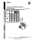
5309942
General Repair Information
Pressure Relief Procedure
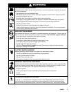
WARNING
INJECTION HAZARD
System pressure must be manually
relieved to prevent system from starting
or spraying accidentally. Fluid under high
pressure can be injected through skin and cause
serious injury. To reduce risk of injury from injec-
tion, splashing fluid, or moving parts, follow Pres-
sure Relief Procedure whenever you:
D are instructed to relieve pressure,
D stop spraying,
D check or service any system equipment,
D or install or clean spray tip.
1. Turn pressure to zero.
2. Turn ON/OFF switch to OFF.
3. Unplug power supply cord.
4. Hold metal part of gun firmly to grounded metal
pail. Trigger gun to relieve pressure.
5. Lock gun safety latch.
6. Open prime valve. Leave prime valve open until
ready to spray again.
If suspected that spray tip or hose is completely
clogged, or that pressure has not been fully relieved
after following steps above, VERY SLOWLY loosen tip
guard retaining nut or hose end coupling to relieve
pressure gradually, then loosen completely. Now clear
tip or hose obstruction.
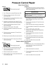
CAUTION
To reduce risk of pressure control malfunction:
D Use needle nose pliers to disconnect wire. Never
pull on wire, pull on connector.
D Mate wire connectors properly. Center flat blade of
insulated male connector in female connector.
D Route wires carefully to avoid interference with
other connections of pressure control. Do not pinch
wires between cover and control box.
1. Keep all screws, nuts, washers, gaskets, and
electrical fittings removed during repair proce-
dures. These parts are not normally provided with
replacement assemblies.
WARNING
ELECTRIC SHOCK HAZARD
MOVING PARTS HAZARD
HOT SURFACE HAZARD
To reduce risk of serious injury, including
electric shock, do not touch moving or
electrical parts with fingers or tools while
testing repair. Shut off and unplug spray-
er when inspection is complete. Install all
covers, guards, gaskets, screws, wash-
ers and shroud before operating
sprayer.
2. Test repair after problem is corrected.
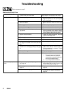
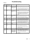
3. If sprayer does not operate properly, review
repair procedure to verify procedure was done
correctly. If necessary, see Troubleshooting, pages
6 – 9, for other possible solutions.
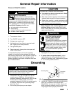
Grounding
WARNING
Improper installation or alteration of grounding plug
results in risk of electric shock, fire or explosion
that could cause serious injury or death.
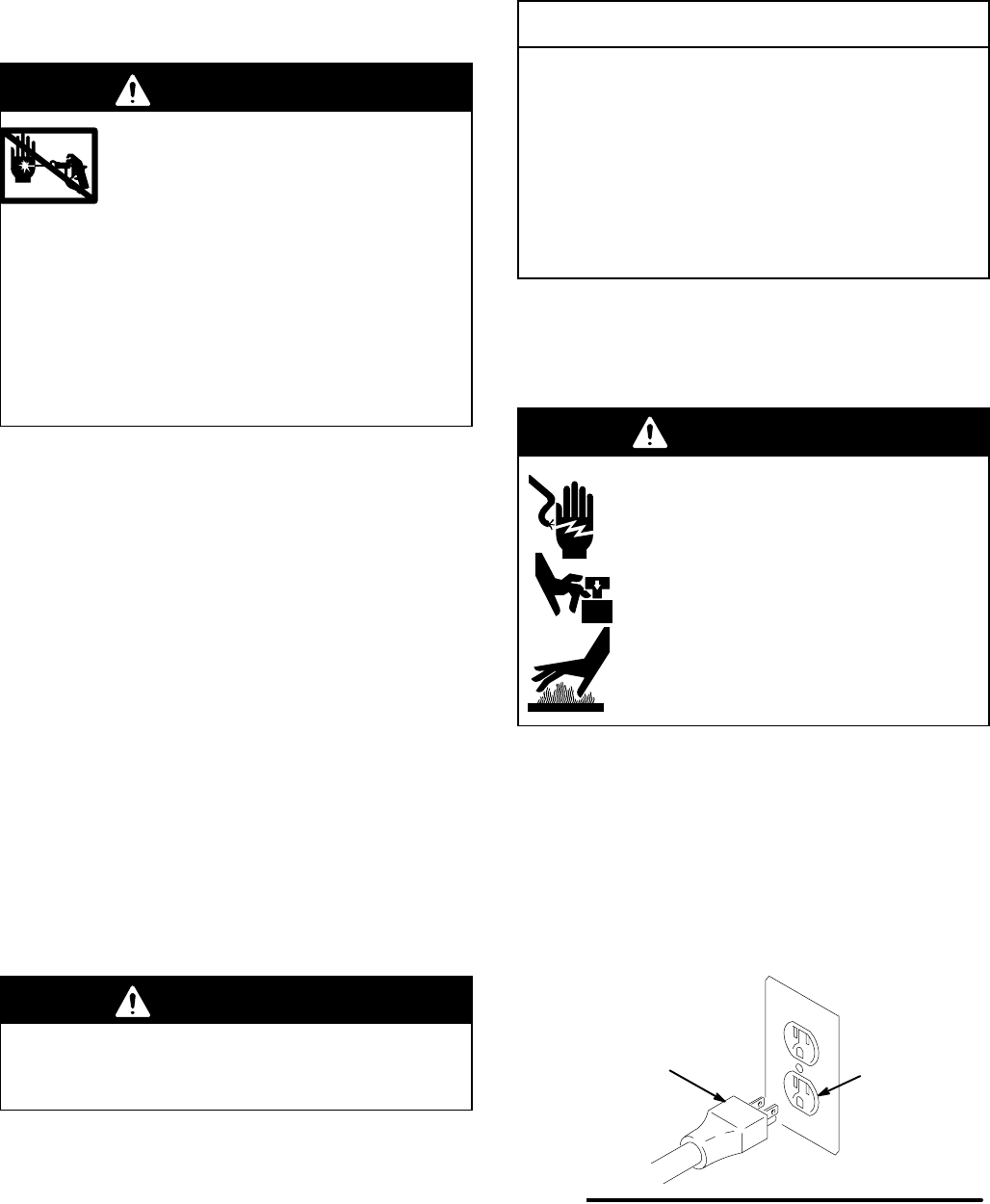
1. Ultimate Mx II 695, 795 and 1095 100–120 Vac
models require a 50/60 Hz, 15A circuit with a
grounding receptacle. Ultimate Mx II 1595 120 Vac
models require a 50/60 Hz 20A circuit with a
grounding receptacle; 220–240 Vac models require
a 50/60 Hz, 10A circuit with a grounding recep-
tacle. See Fig. 2.
2. Do not alter ground prong or use adapter.
Fig. 2
Grounding Plug
Grounded
Outlets
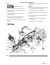
3. 120 Vac: A 12 AWG, 3 wires with grounding prong,
300 ft (90 m) extension cord may be used.
220–240 Vac: You may use a 3-wire, 1.0 mm (12
AWG) (minimum) extension cord up to 90 m long.
Long lengths reduce sprayer performance.