


OPERATING PROCEDURES
OPERATION ADJUSTMENTS
Adjust the Dispense Valve for proper operation as follows. See step 4 for volume adjustment.
1. Make sure that all the Dispense Valve connections are in place.
2. Connect the material for dispensing. Position a container to catch the dispensed material. Cycle the
Dispense Valve until you are getting consistent dispensing (no inconsistencies in the dispensed material,
symmetrical deposit shape).
NOTE: Air entrapped in the material can cause inconsistencies in the dispensed material.
3. Weigh or measure a sample of the dispensed material to see if the volume is correct.
4. To adjust the volume, loosen the set screw
and adjust the stroke adjustment collar on the top of the Dispense
Valve. Raise the adjustment collar to increase volume and lower the collar to decrease volume. Snug the set
screw.
5. Repeat the above steps until you obtain the desired shot size.
6. Adjust the time delay so that the Dispense Valve is able to dispense completely before the valve reloads.
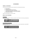
PERIODIC MAINTENANCE
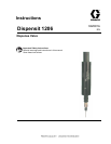
The model 1206 Dispense Valve has been engineered for easy cleanup.
WARNING: Do not attempt any disassembly or cleaning of the unit while it is under pressure.
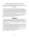
DISPENSING NEEDLE
Remove the luer lock dispensing needle by grasping at the base and twisting one-quarter turn counter clockwise.
Clean with water or solvent depending on the material dispensed. A fine wire, used cautiously, will help open
clogged needles. Replace if damaged or clogged. Replacement needles can be ordered for the Model 1206
Dispense Valve by specifying the proper part number seen in the Recommended Spare Parts section in this
manual.
DISASSEMBLY
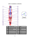
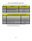
Refer to the illustration below and the drawings for your exact model at the back of this manual.
WARNING: When disassembling multiple valves, do not mix parts. Metering rods are matched with their
sleeves and cannot be interchanged. Some o-rings are the same size but a different color. Be sure to note which
color o-ring is installed in which location.
1. Disconnect the air pressure lines and material line and remove the valve from its mounting. If your valve is
equipped with option Cycle Detection, note the position of the sensors, loosen the set screws and remove the
sensors.
2. Loosen the Socket Head Set Screw (18) and unscrew the Stroke Adjustment Collar (1).
3. Carefully, unscrew the Metering Rod/Sleeve Assembly (7) from the Top Cylinder Block (17).
4. Carefully, push the Piston (2) out of the Top Cylinder Block (17). Remove the O-ring (19).
5. Remove the Metering Rod head (21) from the Piston (2).
6. Take out the upper Retaining Ring (3) and remove the upper Washer (16).
7. Remove the Seal Separator Rod (6). Then remove, in order, the lower Retaining Ring (3), the lower Washer
(16), and Posipak Seal (20).
8. Lift out the Seal Separator Block (5).
9. Remove the Needle Adapter (10).
NOTE: Be alert to the presence of the Check Valve Spring (11) and Check Valve Poppet (13)
in the Needle Adapter (10) as these parts will be loose, and can be easily lost.
10. Carefully, remove the Check Valve Spring (11) and then the Check Valve Poppet (13).
11. Remove all of the remaining seals and o-rings.
Page 6