


PERIODIC MAINTENANCE
ASSEMBLY
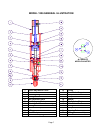
Refer to the illustration above and the drawings in the back of this manual for your exact model.
Note: Clean all valve parts with an appropriate solvent prior to reassembly. Always install new, lubricated
O-rings and seals when assembling the valve. Use Krytox 203GPL (part number 84/0200-K3/11) for lubricating
valve parts including seals and o-rings. Apply a very thin film of lubricant to the inside diameter surfaces of the
Top Cylinder Block (17), the outside of the Metering Rod (21) and to the seals and o-rings. Check the Metering
Rod/Sleeve Assembly (7) for wear and if it is worn secure a replacement before proceeding.
Note: Use caution as you install new U-cup and Posipak seals so that they are not pinched or torn. Do this by
making sure they are lubricated, and by tucking the lips of the seal inward before uniformly pushing them into
position.
1. Insert the lubricated Posipak Seal (14) lip side down into the Metering Rod Sleeve (7).
2. Insert the Seal Separator Block (5).
3. Install, in order, the lubricated Posipak Seal (20) lip side up, the lower Washer (16), and the lower Retaining
Ring (3).
4. Install the Seal Separator Rod (6), aligning the cross-hole so that the metering rod can pass through it.
5. Insert the Metering Rod (21) carefully through the lower Retaining Ring (3), the lower Washer (16), the
Posipak Seal (20), the Seal Separator Block (5), Seal Separator Rod (6) and the Posipak Seal (14).
6. Install the lubricated U-cup Seal (15) lip side down into the Top Cylinder Block (17).
7. Install the upper Washer (16), then the upper Retaining Ring (3).
8. Install the lubricated O-ring (4) on the Piston (2).
9. Install the lubricated O-ring (19) into the Top Cylinder Block (17).
10. Insert the Piston (2) with O-ring (4) part way into the Top Cylinder Block (17) carefully so that the piston
threads do not damage the Posipak Seal (14). Position the piston to accept the head of the metering rod.
11. Insert the Metering Rod head (21) into the Piston (2).
12. Screw the Metering Rod/Sleeve Assembly (7) into the Top Cylinder Block (17).
13. Install the lubricated O-ring (9) on the Metering Rod/Sleeve Assembly (7).
14. Install the lubricated O-ring (12) carefully over the threads of the Needle Adapter (10).
Note:If the valve has the alternate needle adapter, install the outside O-ring (22).
15. Insert the lubricated O-ring (8) into the Metering Rod/Sleeve Assembly (7). Use a blunt tool to seat the o-ring
firmly.
Note: For .188 diameter rod models, first insert the Plastic Washer (8A) into the Metering Rod/Sleeve
Assembly (7), followed by the O-ring (8). Then, use a blunt tool to seat the o-ring and washer firmly.
16. Insert the Check Valve Poppet (13) into the Check Valve Spring (11). Insert the check valve poppet/spring
assembly into the Needle Adapter (10).
17. Screw the needle adapter/check valve spring/poppet assembly firmly into the Metering Rod/Sleeve
Assembly (7).
18. Screw on the Stroke Adjustment Collar (1).
19. Tighten the Socket Head Set Screw (18).
20. Mount the valve and connect the air lines. If your valve is equipped with optional cycle detection, install the
sensors and tighten the set screws.
The model 1206 Dispense Valve is now ready to be placed back into service.
Page 8