


5.
Remove from base the
10
qallon pail pro-
vided. Wipe clean
its
interior
and
pour
<ntO
it
material stirred
and
thinned
to
the proper spray
consistency
or
place a smaller container
of
ma-
thoroughly making sure there
is
no
heavy pigcent
terial
inside the
10
gallon pail. Stir material
concentration
or
cake formed
on
the bottom
of
the
prevent them from clogging the
fluid
intake
container. The pigments must be well dispersed
to
strainer
205-306
when
the
pump
is
initially lower-
ed into the container of material.
NOTE:
Fa
a
small
container, such
as
a one
gallon can. the material intake strainer
must
be
removed
in
order to
get
the
lower
pump housing and
the agitator propellor into the container.
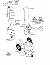
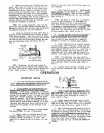
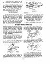
6.
Check
the
position
of
Poot valve feet
in
relation
to
the perforated plate 162-363
of
pump
fluid intake strainer. When
the
plate and screen
are held
in
position by the retaining ring 162-Ll6,
port the perforated
plats
162-361 as show
in
the feet
of
foot valve body
must
contact and
SUp-
Fig.
3.
PUMP
FOOT
FIG.3
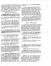
should
be
used
with
spray
tips
havin$
larger
ori-
fice openings.
manual elevator, unhook hanger to lower.
with
Dneumatic elevator, loner by disconnecting
air hose 160-023
from
elevator air line fitting.
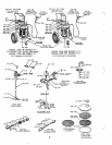
Refer to Fig.
1.
7.
Lower pump into
material.
If
unit
with
bv air,
is
set
at
factory.
If
adjustment
is
necessary, loosen lock
nut
of
air
restrictor
valve 203-743 and turn reetrictor screw'cloclcwise
to decrease
or
pg~e~c~o&+.~e to
&rcase.
Lock
screw
in
place with lock
nut
when adjustment
is
ed atop elevator tube. Refer to
Fig.
1.
completed. Airrestrictor valve 203-743
is
locat-
NOTE:
The speed at which
unit
is
elevated,
8.
If
unit includes a filter kit
205-521
or
a filter kit
205-523
and a surqe tank 205-476,
refer to illustrated
inrt.ruetions
in
senarate
Form 306-696
for
easy conversion
of
manifold
205485
to a filter
or
a
filter-surp
chkaher.
.~
-~
~.
'~~
-
~"
ing hose into a waste container. Start pump
by
opening
ON-OFT
pump
air petcock 202-338 and set-
Allow pump to operate until all traces
of
rust
ting regulator 205-360 at
30
p.s.i.
Refer
Fie
1.
inhibiting
oil,
with which pump
was
treated,
is
removed. Stop pump and discard.materia1 pumped.
9.
Insert delivery end
of
material dispens-
NOTE:
If
accessories have been added to
unit
for
two
gun
operation, open material shutoff
valves 205-583 and
insert
ends
of
both hoses into
waste container before starting pump. Refer to
Fin.
2.
NCrPE:
If
desired, the
100
mesh screen
in
.-
strainer 205-306 can be removed and reulaced
with
10.
Connect swivel 204-940, attached to free
the extra, more coarse
50
mesh screen i62-746 sup-
end
of
material dispensins hose;
to
spray
gun
plied. Refer to Fig.
3.
This
50
mesh
screen
inlet
,
-
OPERATION
IMPORTANT
NOTES
1.
For most satisfactory operating condi-
tions, locate pump and
material
so
that thev
rrill
not
be
sub,iected to temperatures below 65" F.
taininq
heaw fillers.
dirt
or
other coame
ed and skinned
materials
that
vill
not pass freely
particles. Coarse gsind, coagulated, contaminat-
being used, without clogging, can not
be
satis-
through
the openings
in
size
of screen
or
filters
factorily sprayed.
Due
to
the extremely
small
OrVice diameter
in
spray tip through which
ma-
terial
must
be forced under pressure,
it
is
very
orifice are not present
in
the
material to
be
important that particle's which could plug this
Sprayed.
2.
Do no.t attemut to surav materials con-
and clean filter,
if
used,
of
spray
gun.
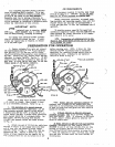
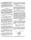
3.
Dailp,
before starting to spray, remove
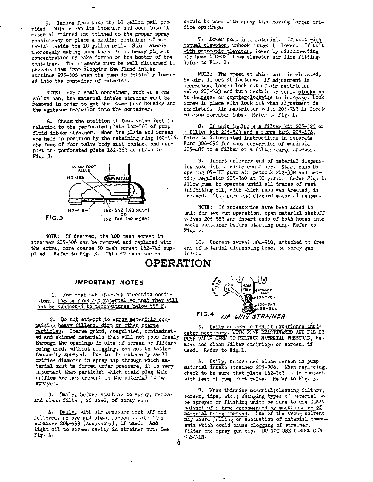
relieved, remove
and
clean screen
in
air
line
light
oil
to screen cavity
in
strainer nut. See
strainer
20L-959
(accessol-g),
if
used.
Add
Fig.
4.
4.
&l~,
wit> air pressure
shut
off
and
5
cates necessary,
WITH
PLMP
DEACTIVATED
AND
FILTER
"P
VAL'?
OmN
TO
RELEEVE
MATERIAL
PRESSRE,
re-
5..
Dailv
or
more often
if
emerience
Ldi-
move and clean filter cartridge
or
screen,
if
used. Refer
to
Fig.
1.
material
intake strainer 205-306. men replacing,
check to be
sure
that plate 162-363
is
in
contact
with feet
of
pump foot
valve.
Refer to Fig. 3.
6.
w,
remove and clean screen
in
pump
screen, tips,
etc.; changing types of material to
7.
When
thinning materia1;cleaning filters,
be sprayed
or
flushing unit; be sure to
we
CLEAW
material beme snrayed. Use of the
wrong
solvent
solvent of a twe rec&mended
bv
manufacturer
Of
may
cause
jellinn
or
separation of
material
compo-
filter and spray
pn
tip.
W
NOT
USE
COMMCN
CLW
ents which-could-cause clogging
of
strainer,
CLEA"JER.