


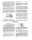

5.
If
suree tank
205-L76
is
beine used with- trigger of spray
'gun
and open air
line
petcock to
out
filter
Darts
installed,
it
should be drained
start
pump.
Allow
pump
to operate long enough
to
as often as experience indicates necessary. Stop
fill
hose and spray qn with solvent.
~~~p
unit
pump and open dump valve. After material has
drained completely
from
tank, close dump valve.
filled with solvent OVerniQht
or
breekend until
readv to soray aeain.
6.
Shut off air pressure to unit and relieve
cressure
in
air line, before removins screen 9. Eecirculate solvent
for
about
5
minutes
156-967
in
air
line
strainer 20k-999 (accessory
if
,
Pior to char&% anit with material.
llsed). Daily,
clean
this screen and at reassembly
edd
light oil to screen cavity
in
nut 156-944. Re-
10.
Close Spray
gun
and raise pump. Start
fer to Fig.
L.
operating, by squeezing trigger of spray
gun
and continue ooeratinn until most
of
solvent has
FLUSHING UNIT
been blown
out
of
sysiem.
Drain excess solvent
from loops
in
hose and fnter
or
surge chamber.
~ ~~ ~~
The frequency vith which unit should be flush-
if
used. After draining tank of
filier
or
sur&
ed deoends upon
type
or
types
of
material pumped, chamber, close
its
dump valve.
generil operating conditions, and usage of unit.
It
is
wi5e to establish
a
re&= flushing scheU-
ule.
In
some instances
it
may be desirable to
flush unit dailv while
in
other cases less freouent
flushing may prbve satisfactory. unit
must2
flushed
at
the end of each wurkine
week.
Thorough-
17
flush
unit with thinner
or
solvent
of
type re-
~~ ~~ ~~~~~
commended for use with the material,
as
follows:
lower pump into container, connect
air
hose to
agitator and charge unit with properly mixed
material.
11.
Replace container of material upon base,
NOTE:
When chansins colors
or
incompatible
EVER,
a
lonaer circulation oeriod
will
necessarilv
tmes of material, flush
unit
as described,
HOW-
be required-and
in
some casks a second flushing
-
1.
Remove Spray tip and
glm
filter cartridge, using thinner oi'solvent may be necessary.
if
used,
from
spray
Sun
and
soak
in
clean recommend-
-
Also
if
manufacturer of another
type
of
material
ed
.type
solvent.
to be sprayed recommends usins
a
different trpe
of
thinner
or
solvent, the thinner
or
solvent used
in
connect ak'hose to agitator and connect
it
to
elevator to raise unit
or
manually
raise and
the possibility of separation
or
jelling of
ma-
terial components. The sur3e tank
or
tank of
hook hanger over truck ha.ndle. manifold
or
filter should be removed and par.ts
thoroughly scrubbed clean. Surge
tank
is
equipped
3.
With
PmP
air petcock
202-338
open, direct Tvith
a
removable
plur:
to
facilitate
cleaning.
2.
With
air
SUPPlY
to
unit
turned
On,
dis-
the
first
flushing
must
be flushed out to eliminate
spray
gun
into
material container and
start
pump
operatink by squeezing trigger of spray
gun.
Unit
rrill
pump air, forcing the material out
of
the
flushed Out as much Daterial as possible, Stop
Pump
ofled with
a
light
air
motor
oil,
whenever
system
back into container. When the
air
has Agitator air motor 101-687
must
be properly
and open manifold dump valve.
Drain
excess materi-
is
shutdorm
or
is
not to
be operated
for
a
period
a1
from
all
loops
in
hose. After material has
stopped draining, close manifold dump valve.
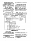
AGITATOR
Of
8
hours
or
more.
All
compressed air oontains
some moisture and
if
air
motor
is
not
nrouerlv
~ ~ .~
.-~~
lubricated before shutdown,
rust
may
result." To
L.
Remove container
of
material from base and
oil
motor:
position
in
its
dace a pail containine. approxi-
mately
2
gallons'
of
comGtible solvent: Loxer pump
into pail of solvent.
direct
gun
to material container and trigger
gun
to
start
pump.
Runp
will
move the solvent, under
cavities of manifold and filter
or
surge tank. When
pressure through the system, flushing the internal
in
system and remove spray
ppn.
solvent appears at
gun,
stop
pump,
release pressure
5.
Set air to pump at approxhately
20
p.s.i.,
1.
Remove oiler screw from air motor top.
2.
Apply
3
to
L
droos
of oil to oiler.
3.
Replace oiler screw and run motor
for
about
1/2
minute.
Air
motor should require
no
attention other
than to be oiled. However,
if
too heavy an oil
has been used
or
other improper oiling practices
have been followed
guming
of rotor
may
result,
imwhich case
air
motor should be flushed
as
6.
Remove spray
gun
from
hose and thorou5hly
clean
in
accordance with procedure outlined in
separate Instruction Sheet for the spray
gun.
Keep
spray
gun
head immersed
in
solvent until attached
to hose again.
follows:
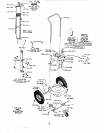
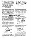
OILER
SCREW
161-41
7.
Direct end
of
material hose into pail of
solvent and
start
pump by opening air line petcock
202-338.
Allow
thinner
or
solvent to circulate
through system and back into pail
for
a period
of
10
to
15
minutes. Wash
material
from
exterior of
lower immersion pump.
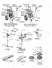
FIG.
5
8.
After thoroughly flushing unit stop pump
1.
Remove exhaust muffler
161-415.
Fill to
aP.d connect material hose to spray
gun.
Squeeze overflowing with kerosene.
~~~l~~~
muffler.
a
.,