


,
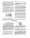
Pig.
5.
Fill
oiler
with
kerosene. Replace oiler.
'
2.
Remove
oiler from
air
motor top cap. See
>.
.
3.
dllow a
soaking
period of,
5
to
10
minutes,
then start ab motor.
Run
motor
slowly.
After
smooth operation has been achieved
and
kerosene
has
been
blown
from
a*haUSt. stop
LUOtOr,
remove ouer
screw and
fFu
oiler with a light
air
motor
oil.
MUl'a.
If
it should need repab, contact
pour
NOTE:
MAgE
NO
ATPMPT
M
DISASSMBLB
ADl
nearest Graco Authorized %mice Depot.
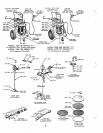
FLUID SHUTOFF VALVE
205-583
(ACCESSORY\
Worn
"0"
rings,
ball
seat
or
ball
may
cause
valve to fail to operate.
If
sesvice
is
necessary,
shut off
air
supply, relieve
fluid
pressure
and
re-
move valve. Place valve body in a vise and drive
valve cap
from
body
being
careful not to
turn cap
the two pina out of holes
in
valve
body.
Runwe
..
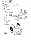
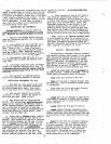
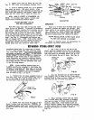
fIG.6
ELEVATOR
LUERICATION
Every
2
to
6
weeks
with
elevator free
of
air
pressure,
unscrew
and
remove cap
&-ab.
Fill
oil.
Replace cap. Raise elevator
and
lubricate
inner carity of cup leather
150-179
vith
SdE
20
exposed surface of elevator guide tube
1&-7A7.
See parts illustration for location of parts.
as this would shear off the locating pins in
valve
body.
See
Fig.
6.
Disassemble and replace
any
PUMP. REGULATOR,
SPRAY
GUN AND
worn
or
damaged parts. NOTE:
With
handle removed,
"On
ring
15L,-7lJ
can be best removed
by
first re-
moving
ball
162-831.
from
body
and then pushing
handle shaft down
intb
cavity in valve
body'.
FILTER OR SURGE CHAMBER
Refer to separate sheet
for
maintenance
in-
structions and parts identification.
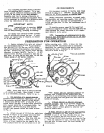
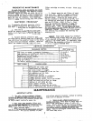
REPAIRING HYDRA-SPRAY HOSE
dra-Spray hose
is
constructed of tiupont
" inner
lining
tube with stainless steal
vires, position assembly.block
vith
Its
groovad
wire braid
Outer
CWer. This hose
is
exoensive
side toward end of hose just cut and slide block
becane damaged it can be salvaged
by
assembling
of
an
inch beyond the end of hose. See
Fig.
8.
and should be handled with care.
If
hose should
onto hose until
it
protrudes about
1/32
to
1/16
Couplings to
the
broken
ends
of
hose sections.
Graco detachable
and
reusable couplings consist
Of two parts. the female Mvel stud
201.-937
and
no.
F-20198
the sleeve
162-366.
and are assembled upon hose
. . ~
in the following
manner:
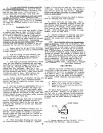
3. Add a drop of oil to the end
of
the
ASSEMW
moL
CIUIION-
or
rmrunc
DO
NOT
CRUSH
HO5L
F-20898
specifically designed to facilitate the
assembly of couplbgs upon this tppe of hose
may
be obtained
from
factory. This fixture consists
of a thu piece assembly block and
an
assembly
tool
as
shown
in
Fig.
7,
8
and
9.
NUTE:
A hose coupling fixture Graco
No.
.
1.
Position the two piece assembly block on.
,jvW
ass&ly twl
as
shown
in
Fig.
8
and while
4.
ap the threaded e.nd
of
sleeve 162-366
be cut
and
clamp
in
a dse
as
shown
in
Fig.
7.
hose
With
plain side of block
toward hose end to holding block
in
place
on
hose, insert end of tool
Cut off With a fine tooth hand
hack saw.
into hose and end of sleeve into groove.
2.
Remove hose
from
block
and
grip
In
vise
about
2
inches
from
end just cut.
CAUTION:
00
not crush the hose-apply
only
enough pressure
on the viae jaws to hold while forcing the sleeve
onto hose.
vith a wrench apply
body
pressure to
assembly
5.
While twisting sleeve
back
and
forth
td and
as
sleeve
is
forced onto hose
allow
block to slide back. After about
&
inch
Of
hose
is
covered, remove the block and continue
to force sleeve onto the hose until end of hose
reaches the
shoulder
in
sleeve. Refer to
Fig.
10.
9
PTFEPTFEPTFE