


12 308253
Service
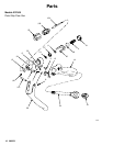
Complete Disassembly and Assembly
of the Gun (continued)
Assembly
1. Follow steps 9 to 11 on page 10.
2. Lubricate the o-rings (5 and 6) and install them into
the gun body.
3. Follow steps 12 to 14 on page 10.
4. Lubricate the trigger pivot holes (a) bracket guide
(b), and rod (13).
5. Install the trigger (29) with the rod (13) and retain-
ing rings (8).
6. Lubricate the thread and o-ring sealing surface on
the valve seat nut (26). Torque the valve seat nut
into the gun body (17) to:
Models 235627, 237607, and 237649: 70–80
in-lbs (7.9–9.0 NSm).
Models 235628 and 243775: 100–125 in-lbs
(11.3–14.1 NSm).
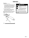
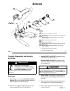
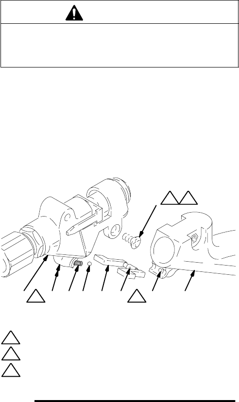
7. Lubricate the trigger lock housing area (c) and
apply low strength anaerobic sealant to the screws
(9). See Fig. 5.
8. Install the spring (7) into the gun body (17). Place
the ball (2) in the center of the spring.
9. Align the trigger lock detent (d) with the ball (2).
Compress the ball (2) and spring (7) with the
trigger lock (15) until the trigger lock is seated in
the housing.
10. While holding the trigger lock (15) in place, install
the gun handle (14). Secure the gun handle with
the screws (9). Torque the screws to 6–10 in-lbs
(7.9–9.0 NSm).
11. For model 237649, if the inlet fitting (19) and fluid
tube (18) were disassembled, apply pipe thread
sealant compound to the inlet fitting (19). Install
the inlet fitting into the fluid tube (18). Torque the
fitting to 110–130 in-lbs (12.4–14.7 NSm).
12. Install the fluid tube (19) through the gun handle
(14) and screw it into the gun body (17). Torque
the fluid tube (19) to:
Models 235627, 237607, and 237649: 50–60
in-lbs (5.6–6.8 NSm).
Models 235628 and 243775: 200–250 in-lbs
(22.6–28.2 NSm). Secure the fluid tube with the
setscrew (42), and torque the setscrew to 6–10
in-lbs (0.7–1.13 NSm).
CAUTION
To avoid loosening the connections and damaging the
gun, grip the gun body (17), not the handle (14), when
tightening the fluid tube (19).
13. Adjust the free travel of the trigger as instructed
under Adjusting the Valve, page 9.
14. Follow steps 15 to 19 on page 10 to finish assem-
bling the gun.
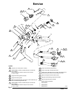
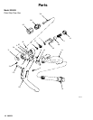
Fig. 5
01806
17 7 2 15
9
dc14
F
c
F
A
M
NOTES:
Torque to 6–10 in-lbs (0.68–1.13 NSm)
Apply lithium base grease
Apply low strength anaerobic sealant (blue)
A
F
M