


16 307741
Service
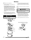
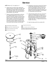
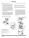
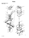
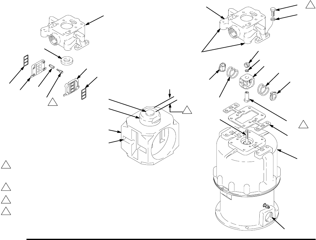
NOTE: Refer to Fig. 8 for steps 11 to 16.
11. Place the gasket (38*) on top of the cylinder (36).
12. Thread the hub (10) onto the trip rod (40). Lift the
rod and grasp it with the padded locking pliers.
Screw the hub down as far as possible by hand.
13. Install the air valve housing (5), lockwasher (6),
and trip rod nut (7) so the nut is flush with the top
of the trip rod (40). Tighten the nut 2 turns more,
so there is 1 mm (0.04 in.) clearance between the
top of the rod and the top of the nut. Hold the flats
of the trip rod nut with a wrench. With another
wrench, tighten the hub (10) to 28–34 NSm (21–25
ft-lb). Release the pliers.
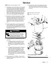
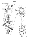
14. Place the plate seals (1) on the valve plates (2).
Place the plates in the air manifold (20). Install the
adjusting screw (11) and nut (12) assemblies in all
four corners of the plates. Important: Adjust the
screws and nuts evenly so they snugly hold the
plates. Do not exceed 4 NSm (35 in-lb).
15. Install the rubber pad (8) in the air manifold (20).
NOTE: On Model 235525, check that the plugs (9) are
in place in the air manifold exhaust ports (E).
On Model 237000, check that the tubing (82) is se-
curely attached to the air manifold (20). See page 22.
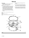
16. Place the springs (4) and air director valves (3)
into the valve housing (5). Hold the springs and
valves in place and install the air manifold (20)
over the housing, making sure it is properly ori-
ented. The exhaust ports (E) must be oriented to
the optional outlet (L) of the base as shown. Be
sure the valve housing (5) moves up and down
freely, and then install and tighten the screws (31)
and lockwashers (13) holding the manifold (20) to
the cylinder (36).
02963
Fig. 8
Torque to 28–34 NSm (21–25 ft-lb)
2
3
Make top of nut flush with top of trip
rod, then tighten 2 turns more.
Top of nut (7) must be 1 mm (0.04”)
from end of rod (40).
1
C
40
7
5
1
Detail of Valve Housing
31
13
36
3
4
10
7
6
5
38*
40
4
3
07282A
Torque to 34 NSm (25 ft-lb).
Tighten snugly. Do not exceed 4 NSm (35 in-lb).
20
11
12
8
2
1
Detail of Air Manifold and Valve Plates
1
2
4
20
L
2
3
4
E