


11309411
Pinion Assembly/Rotor/Shaft/Clutch/Pulley
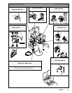
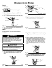
Removal
1. If pinion assembly (4) is not removed from clutch
housing (169), do 2. through 5. Otherwise, do 2.
and then start at 6.
2.
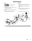
Relieve pressure; page 6.
3. Disconnect field cable (X) from pressure control
and reed switch (A).
Fig. 4
X
Bottom View
A
ti1842a
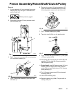
4. Fig. 5. Remove five screws (47) and lockwashers
(37) and pinion assembly (4).
47
37
47
37
Fig. 5
4
ti1888a
5. Fig. 6. Place pinion assembly (4) on bench with
rotor side up.
6. Remove four screws (16) and lockwashers (37).
Install two screws in threaded holes (E) in rotor.
Alternately tighten screws until rotor comes off.
Fig. 6
E
16
37
8701B
7. Fig. 7. Remove retaining ring (169b).
8. Tap pinion shaft (169c) out with plastic mallet.
Fig. 7
169b
169c
8703B
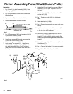
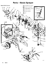
9. Fig. 9. Remove belt guide bracket (171), belt guard
(117) and vee belt (103).
10. Hold pulley (53) and remove four screws (88) and
washers (37) from hub (94). Remove armature
(86) and spacer (169f).
11. Engine Detail, page 20. Remove screw (101) and
washer (166) from engine drive shaft. Remove
pulley (53) and motor shaft sleeve (170). Remove
pulley and key (41).
12. Fig. 9. Remove three screws (63) from beneath
mounting plate (D).
13. Lift off clutch housing (169).
14. Remove retaining ring (169b). Pull jack shaft as-
sembly (169c) out.