


12 309411
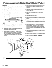
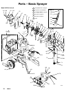
Pinion Assembly/Rotor/Shaft/Clutch/Pulley
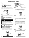
Installation
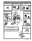
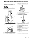
1. Fig. 9. Install jack shaft assembly (169c). Install
retaining ring (169b).
2. Fig. 8. Lay two stacks of two dimes on smooth
bench surface.
3. Lay armature (86) on two stacks of dimes.
4. Press hub (94) down on bench surface.
Fig. 8
86
8705A
0.12 ±.01 in. (3.0 ±.25 mm)
dimes
94
5. Fig. 9. Place spacer (169f) and armature (94, 86)
on jack shaft assembly (169c).
6. Install three screws (63) through mounting plate
(D) and into clutch housing (169).
7. Apply Loctite
R
to screw (101). Install screw,
washer (166), key (41) and pulley (53) in end of
jack shaft assembly (169c). End of jackshaft
(169c) must be 0.090 in. below flush with end of
bushing.
8. Hold pulley (53) and install four screws (88) and
washers (37) in hub (94). Torque to 125 in-lb
(14 Nm).
9. Install belt guard (117), belt guide bracket (171)
and vee belt (103).
10. Fig. 7. Tap pinion shaft (169c) in with plastic
mallet.
11. Install retaining ring (169b).
12. Fig. 6. Place pinion assembly on bench with rotor
side up.
13. Apply Loctite to screws. Install four screws (16)
and lockwashers (37). Alternately torque screws
to 125 in-lb until rotor is secure.
14. Push pinion housing (4) assembly onto clutch
housing (169e). Tap lightly on front of bearing
housing (17) with a plastic mallet to push drive
housing and pinion housing assembly onto clutch
housing.
15. Install pinion assembly with five screws (47) and
lockwashers (37).
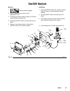
16. Fig. 4. Connect field cable (X) to pressure control.
17. Page 10. Do Drive Housing, Installation.
Fig. 9
37
88
86
169e
169b
41
169c
101 166
103
63
D
169f
171
94
ti1853a
53
117