


14 309411
Pressure Control
Control Board
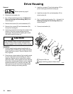
Removal
1.
Relieve pressure; page 6.
2. Fig. 10. Remove four screws (11) and
display/cover (12). Pull display connector wings
open on PC board and pull display connector out.
3. Fig. 17. Disconnect at control board (147):
D Lead (D) from potentiometer.
D Lead (E) from transducer.
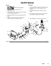
D Remove ON/OFF switch (51) at connector (A).
4. Fig. 10. Remove six screws (44) from control board
(147) and green ground wire.
5. Remove connector (Ref 4) at backside of pressure
control. Remove jam nut (147a) and control board
(147).
Installation
When installing replacement control board, follow
instructions with control board to set model type.
1. Fig. 10. Install control board (147) and jam nut
(147a). Install connector (Ref 4) at backside of
pressure control.
2. Install green ground wire and control board (147)
with six screws (44).
3. Fig. 17. Connect to control board (147):
D Connect ON/OFF switch (51) connector (A).
D Lead (E) to transducer.
D Lead (D) to potentiometer.
4. Fig. 10. Push display connector into PC board
close display connector wings on PC board. Install
display/cover (12) with four screws (11).
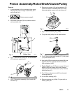
Pressure Control Transducer
Removal
1.
Relieve pressure; page 6.
2. Fig. 10. Remove four screws (11) and
display/cover (12).
3. Disconnect lead (E) from control board (147).
4. Remove two screws (141) and transducer guard
(178) from control housing (8). Pull transducer
connector through rubber grommet (176).
5. Remove pressure control transducer (100q) and
o-ring (100p) from filter housing (100e).
Installation
1. Fig. 10. Install o-ring (100p) and pressure control
transducer (100q) in filter housing (100e). Torque
to 30–36 ft-lb.
2. Install transducer connector and rubber grommet
(176) in control housing (8) . Install transducer
guard (178) on control housing with two screws
(141).
3. Connect lead (E) to control board (147).
4. Install display/cover (12) with four screws (11).
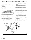
Pressure Adjust Potentiometer
Removal
1.
Relieve pressure; page 6.
2. Fig. 10. Remove four screws (11) and
display/cover (12).
3. Disconnect lead (D) from control board (147).
4. Loosen set screws on potentiometer knob (13) and
remove knob, shaft nut, lockwasher (22) and
pressure adjust potentiometer (22).
5. Remove seal (78) from potentiometer (22).
Installation
1. Install seal (33) on potentiometer (22).
2. Fig. 10. Install pressure adjust potentiometer (22),
shaft nut, lockwasher (22) and potentiometer knob
(13).
a. Turn potentiometer shaft (22) clockwise to
internal stop. Assemble potentiometer knob
(13) to strike pin on plate (50).
b. After adjustment of step a., tighten both set
screws in knob 1/4 to 3/8 turn after contact
with shaft.
3. Connect lead (D) to control board (147).
4. Install display/cover (12) with four screws (11).