


6 308-332
Installation
Be sure that all operators read and understand this
entire manual and the separate manuals supplied with
components and accessories before using this equip
-
ment.
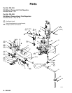
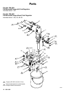
Reference numbers and letters in parentheses refer to
the figures and the parts lists on pages 10–13.
Accessories mentioned are available from your Graco
distributor
. If you supply your own accessories, be sure
they are adequately sized to meet your system’
s
requirements.
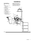
The T
ypical Installation shown in Fig. 3 is only an
example. For assistance in designing a system to meet
your particular needs, contact your Graco distributor
.
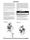
System Accessories
WARNING
Two
required components are supplied with your
pump, to help reduce the risk of serious injury
including fluid injection, splashing in the eyes or on
the skin, or injury from moving parts if you are
adjusting or repairing the pump.
The bleed-type master air valve (B) relieves air
trapped between this valve and the pump. T
rapped
air can cause the pump to cycle unexpectedly
. To
bleed air from the pump, the pump air regulator (F)
must be open when you close this valve.
The fluid drain valve (H) assists in relieving fluid
pressure in the displacement pump, hose, and gun;
triggering the gun to relieve pressure may not be
sufficient.
Install an air line filter (E) in the main air line, to re
-
move harmful dirt and moisture from the compressed
air supply
. T
o provide automatic lubrication of the air
motor
, install an air line lubricator (P) downstream from
the pump air regulator (F). Install a second master air
valve (D) in the main air line, to isolate the accessories
for servicing.
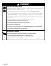
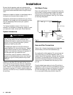
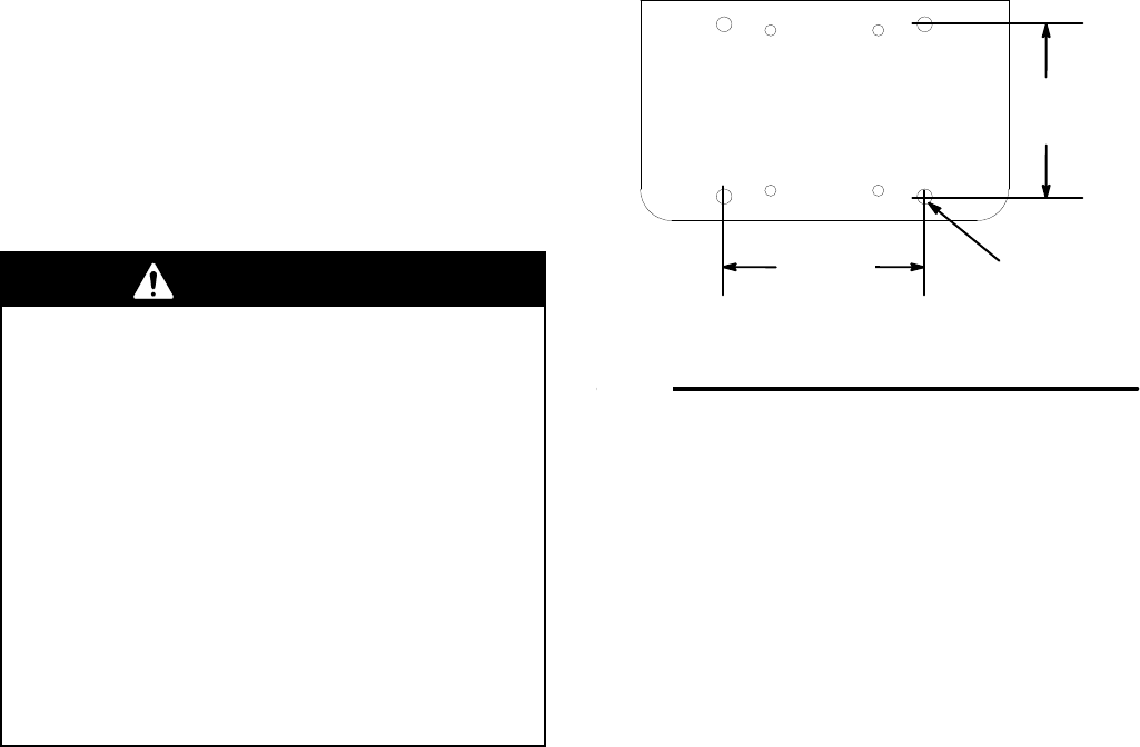
Wall Mount Pump
Mount
the wall bracket 5 ft (1.5 m) above the floor
. Be
sure the wall is strong enough to support the weight of
the pump and accessories, fluid, hoses, and stress
caused during pump operation. See Fig. 2 for a brack
-
et mounting hole pattern.
Fig. 2
02824
Four 0.47
in. (12 mm)
diameter
holes
5
in. (127 mm
)
6.26
in.
(159
mm)
Hose and Gun Connections
Refer
to Fig. 3. Apply thread sealant and screw the
suction hose (J) into the fluid intake elbow (S).
On models with a fluid regulator (R), connect one end
of the fluid hose (L) to the fluid regulator outlet. On
models without fluid regulators, connect one end of the
fluid hose (L) to the outlet of the fluid filter (K). Connect
the other end of the fluid hose (L) to the fluid inlet of
the spray gun (N).
Do not
install the spray tip in the
gun yet.
Close the bleed-type master air valve (B) and the air
regulators (F and G). Connect a grounded air hose (M)
between the outlet of the gun air regulator (G) and the
air inlet of the spray gun (N). The pump air regulator
(F) is connected to the pump (A) with a hose (C).