


7308-332
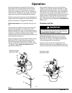
Installation
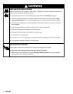
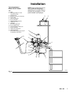
Fig. 3
KEY
A Pump
B Bleed-Type
Master Air V
alve
(required for pump)
C
Air Supply Line
D
Master Air V
alve (for accessories)
E
Air Line Filter
F
Pump Air Regulator
G
Gun Air Regulator
H
Fluid Drain V
alve (required)
J
Fluid Suction Line
K
Fluid Filter
L
Gun Fluid Supply Hose
M
Gun Air Supply Hose
N
Air-Assisted Airless Spray Gun
P
Air Line Lubricator
R
Fluid Pressure Regulator
S
Fluid Intake Elbow
Y
Ground Wire (required; see page 5
for installation instructions)
Typical Installation –
Model 236–067 Shown
NOTE:
Some components shown
are included with the sprayer
,
depending on the model. Refer to
the parts lists on pages 10–13 for
parts included in your sprayer
.
A
B
C
DE
F
G
H
J
K
L
L
M
M
N
P
R
Y
S
02816A