


6
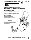
308-457
Setup
III. Unpack the system.
1. In
addition to the assembled components, the air
and fluid hoses, gun and instruction manuals are
packaged separately in the main shipping con
-
tainer
. These are the manuals you should receive:
307–619
23:1 ratio Monark pump
308–176
Air-assisted airless spray gun
307–273
Fluid filter
308–167
Air regulator
308–861
Ball valve
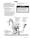
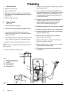
IV. Connect the hoses and gun to the
system. See
Fig. 1.
1.
Connect the blue fluid hose (6) between the fluid
filter and the fluid inlet of the spray gun (3). These
are 1/4–18 npsm(f) swivel fittings.
2.
Connect the red
air hose (7) between the gun air
regulator (8b) and the air inlet of the spray gun (3).
These are 1/4–18 npsm(f) swivel fittings.
3. V
erify that all fittings throughout the system are
tightened securely
.
V. Ground the system.
WARNING
To
reduce the risk of static sparking, ground the
pump and all other equipment used or located in
the spray area. Check your local electrical code for
detailed grounding instructions for your area and
type of equipment.
Ground all of this equipment.
Also read
FIRE OR EXPLOSION HAZARD
on
page 4
.
1.
Pump
: one end of the ground wire (30) is already
connected to the air motor grounding lug. Connect
the clamp end of the ground wire to a true earth
ground.
2.
Air and fluid hoses
: use only electrically conductive
hoses with a maximum of 500 feet (150 m) com
-
bined hose length to ensure grounding continuity
.
3.
Air compressor
: according to manufacturer
’
s
recommendations.
4.
Fluid supply container:
according to local code.
5.
All solvent pails used when flushing
, according to
local code. Use only metal pails, which are con
-
ductive. Do not place the pail on a non-conductive
surface, such as paper or cardboard, which inter
-
rupts the grounding continuity
.