


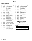
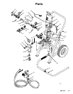


7
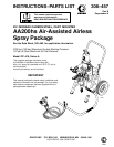
308-457
System
Component Information
I. How to use the air–assisted airless
spray gun.
With
an air-assisted airless spray gun, the spray tip
shapes the fluid into a fan pattern. Air from the air cap
further atomizes the fluid and completes the atomiza
-
tion of the paint tails into the pattern to produce a more
uniform pattern.
The spray gun has a built-in lead and lag operation.
When triggered, the gun emits air before the fluid is
discharged. When the trigger is released, the fluid
stops before the air flow stops. This helps assure the
spray is atomized and prevents fluid buildup on the air
cap.
NOTE:
The gun air and fluid inlets have 1/4–18 npsm
(R1/4–19) compound male threads that are compatible
with NPSM and BSP female swivel
connectors.
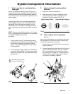
1.
The fan pattern valve (E) can be used to reduce
the pattern by about 25% of the total pattern width.
As the valve is opened, the pattern will reduce
slightly
. The tip used designates the total width of
the spray pattern.
2. T
o unlock the gun trigger safety, turn the safety so
it is parallel with the trigger
. T
o lock the gun trigger
safety
, turn the safety to a right angle with the trig
-
ger
. See Fig. 2.
Fig. 2
UNLOCKED
gun trigger safety
LOCKED gun trigger safety
0795A
1
2
1
2
E
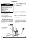
II. How to change the spray pattern
direction.
1. Relieve
the air and fluid pressure.
2.
Install a spray tip in the gun. Rotate the air cap
(the spray tip rotates with it) to determine the
direction of the spray pattern. See Fig. 3.
Fig. 3
V
ertical Spray Pattern
Horizontal Spray Pattern
0791
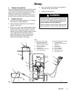
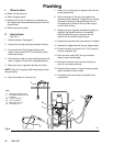
III. How to adjust the air regulators.
See
Fig.
4.
As you look at the system, the air regulator (8a) on the
left regulates air to the gun and the air regulator (8b)
on the right regulates air to the pump.
1.
Always open air regulators slowly to prevent surg
-
ing during startup.
2. T
o open the regulator
, which allows air to flow
, turn
the T–handle IN (clockwise). T
urn the T–handle
OUT (counterclockwise) to close off the air flow
.
Be sure the jam nut under the T–handle does not
interfere with your adjustments. T
ighten the jam
nut to lock in the setting, if desired.
Fig. 4
8a
8b
CW
CCW
04069