


308-548 19
General
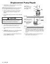
Repair Information
WARNING
INJECTION
HAZARD
T
o reduce the risk of serious injury
,
whenever you are instructed to relieve
pressure, follow the
Pressure Relief
Procedure
on page 9.
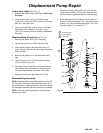
Tool List
These
are the tools required to service all parts of the
sprayer.
3/16” Allen
r
wrench:
gear housing, legs, handle
3/8” Allen
r
wrench:
pump manifold
#1 Phillips
r
screwdriver:
junction box,
pressure control, front cover
3/8” socket wrench:
motor mount
5/8” socket wrench:
drain valve, outlet fittings,
on/off switch boot, piston
13/16” socket wrench:
drain valve
1-1/4” socket wrench:
pump inlet valve
1/2” open end wrench:
pump rod
1
1/16” open end wrench:
piston jam nut
15/16” open end wrench:
flats of inlet tube
1-3/4” open end wrench:
pump jam nut
5/64” drive pin:
drain valve pin
3” needle nose pliers:
wiring, on/off switch
Hammer & punch:
packing nut
T
orque wrenches:
various fasteners
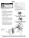
WARNING
MOVING P
ARTS HAZARD
o reduce the risk of serious injury
, includ
-
ing electric shock, DO NOT touch any
moving parts or electrical parts with your
fingers or a tool while inspecting the repair
.
Shut of
f the sprayer and unplug it as soon as you
complete the inspection.
Reinstall all covers, gaskets, screws and washers
before operating the sprayer
.
WARNING
HOT SURF
ACE HAZARD
During operation, the motor and drive
housing become very hot and could burn
your skin if touched. Flammable materi
-
als spilled on the hot, bare motor could cause a fire
or explosion
CAUTION
T
o reduce the risk of a pressure control malfunc
-
tion, be sure to properly mate connectors, and
never pull on a wire to disconnect it. Pulling on a
wire could loosen the connector from the wire.
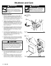
1. When disconnecting wires
in the junction box
assembly
, use needle nose pliers to separate mat
-
ing connectors.
2.
When reconnecting the wires
, be sure the flat
blade of the insulated male connector is centered
in the wrap–around blade of the female
connector.
CAUTION
Improper wire routing can result in poor sprayer
performance or damage to the pressure control.
3.
Route wires carefully through the drive housing
and motor
. A
void pinching the wires between the
junction box and the motor or pressure control.
4.
Keep all screws, nuts, washers, gaskets, and
electrical fittings
removed during repair proce
-
dures. These parts are not normally provided with
replacement assemblies.
5. T
est your repair before regular operation
to be
sure the problem is corrected.
6.
If the sprayer does not operate properly
, verify
that everything was done correctly. Also refer to
the T
roubleshooting Guide, pages 14–18, to help
identify other possible problems and solutions.