


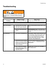
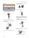

Troubleshooting
310824D 11
Basic Electrical
See wiring diagram, page
28
1. Electric supply. Meter must read
100-130 VAC for 110-120 VAC
models and 210-255 VAC for 240
VAC models.
Reset building circuit breaker, replace building
fuses. Try another outlet.
2. Extension cord. Check extension
cord continuity with volt meter.
Replace extension cord.
3. Sprayer power supply cord.
Inspect for damage such as bro-
ken insulation or wires.
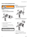
Replace power supply cord. See page 26,
Power Cord Replacement.
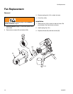
4. Fuse. Check replaceable fuse on
control board (next to ON/OFF
switch).
Replace fuse after completing motor inspection.
See page 22, Fuse Replacement.
5. Motor leads are securely fas-
tened and properly connected to
control board.
Replace loose terminals; crimp to leads. Be
sure terminals are firmly connected.
Clean circuit board terminals. Securely recon-
nect leads.
6. Motor thermal switch. Yellow
motor leads must have continuity
through thermal switch.
Replace motor. See page 27, Motor Replace-
ment.
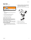
7. Brush cap missing or loose brush
lead connections.
Install brush cap or replace brushes if leads are
damaged. See page 19, Motor Brush
Replacement.
8. Brush length which must be 1/4
in. (6mm) minimum.
NOTE: Brushes do not wear at
the same rate on both sides of
motor. Check both brushes.
Replace brushes. See page 19, Motor Brush
Replacement.
9. Motor armature commutator for
burn spots, gouges and extreme
roughness.
Remove motor and have motor shop resurface
commutator if possible. See page 27, Motor
Replacement.
10. Motor armature for shorts using
armature tester (growler) or per-
form spin test, page 17.
Replace motor. See page 27, Motor Replace-
ment.
11. Pressure control not plugged in
to control board.
Insert pressure control connector into control
board.
Problem
What To Check
(If check is OK, go to next check)
What To Do
(When check is not OK, refer to this column)