


Pressure Control Assembly Replacement
310824D 23
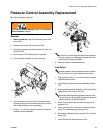
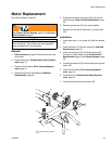
Pressure Control Assembly Replacement
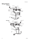
See Wiring Diagram, page 28.
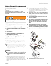
Removal
1. Relieve pressure, page 8. Disconnect power cord
from outlet.
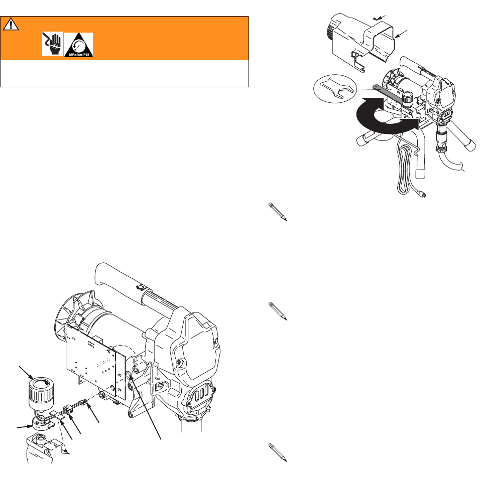
2. Remove two screws (30) and shroud (29).
3. Disconnect pressure switch connector (A) from con-
trol board (33).
4. Remove tape (22) holding wires to manifold.
5. Pull wires back through hole (K) in housing.
6. Turn the pressure control knob (16) counter clock-
wise as far as you can to access the flats on either
side of the pressure control assembly.
7. Using a 1 in. (26 mm) wrench loosen and unscrew
pressure control assembly.
8. Remove pressure control assembly.
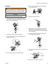
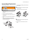
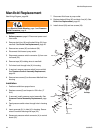
Installation
1. Align grommet collar (17) on fluid manifold so open-
ing faces toward motor.
2. Apply loctite to pressure control assembly threads
(16)
3. Screw pressure control assembly (16) into manifold
and torque to 150 in-lbs (17.0 N.m)
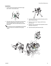
4. Wrap wires around knob and feed through slot in
grommet (21).
5. Insert grommet (21) in hole (K) in housing. Secure
wires to manifold housing with tape (22).
6. Reconnect pressure switch connector (A) to control
board (33).
7. Install shroud (29) and two screws (30).
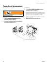
WARNING
Read Electric Shock Warning, page 3 and Pressure
Relief Procedure, page 8.
TIC
A
K
21
22
If you plan to reuse the pressure control assembly,
be very careful not to damage or tangle the wires
while unscrewing the assembly.
Inspect pressure control assembly before installa-
tion to verify the o-ring is installed and in place.
Be careful when tightening pressure control knob
that wires do not get pinched between the pressure
control assembly and fluid manifold.
29
30
ti5766a