


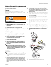
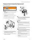
Manifold Replacement
24 310824D
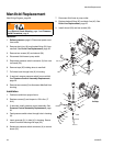
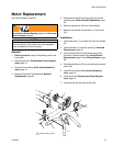
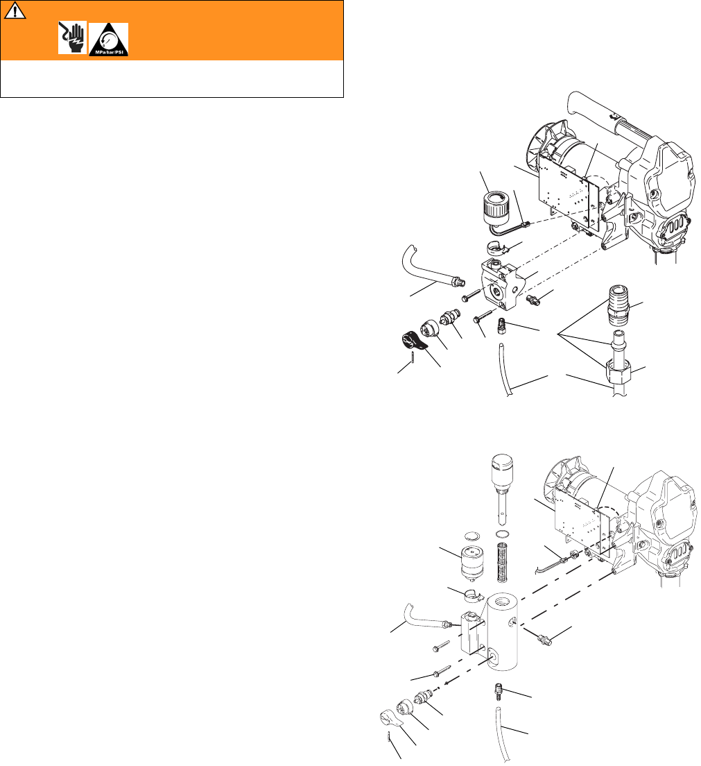
Manifold Replacement
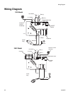
See Wiring Diagram, page 28.
Removal
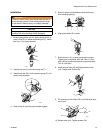
1. Relieve pressure, page 8. Disconnect power cord
from outlet.
2. Remove drain line (40) and barbed fitting (20) from
manifold. See Drain Line Replacement, page 25.
3. Remove two screws (30) and shroud (29).
4. Disconnect fluid hose at pump outlet.
5. Disconnect pressure switch connector (A) from con-
trol board (33).
6. Remove tape (22) holding wires to manifold.
7. Pull wires back through hole (K) in housing.
8. If required, remove pressure switch from manifold.
See Pressure Control Assembly Replacement,
page 23.
9. Remove two screws (6) to disconnect Manifold from
housing.
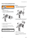
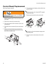
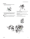
Installation
1. Position manifold on sprayer frame.
2. Replace screws (6) and torque to 150 in-lbs (17
N.m).
3. If removed, install pressure control assembly. See
Pressure Control Assembly Replacement, page
23.
4. Feed pressure switch wires through hole in housing
(K).
5. Insert grommet (21) in hole (K) in housing. Secure
wires to manifold housing with tape (22).
6. Reconnect pressure switch connector (A) to control
board (33).
7. Reconnect fluid hose at pump outlet.
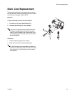
8. Replace barbed fitting (20) and drain line (40). See
Drain Line Replacement, page 25.
9. Install shroud (29) and two screws (30).
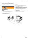
WARNING
Read Electric Shock Warning, page 3 and Pressure
Relief Procedure, page 8.
6
Ref 14
17
A
33
A
18
24
23
20
40
26
13
25
C
B
6
17
15
18
A
A
20
Ref 14
25
26
23
24
13
40
33
ProStep
ti12077a
ti5771a