


Introduction
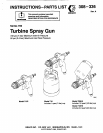
The Series
700
Turbine Spray Gun can spray most and directs the paint from the gun to the surface,
coatings or finishes currently being used for automo-
tive
refinish, industrial, aerospace, marine, wood,
minimizing overspray and increasing transfer em-
plastic and architectural applications.
ciency. This enables painters to comply with new
clean air laws that are designed to reduce
VOC
(vola-
This spray gun typically utilizes
5
psi
(0.35
bar)
tile organic compounds) emissions, eases paint
inbound air pressure to produce high quality paint
application by requiring fewer paint passes to obtain
finishes. The gun produces a cone of air that carries
coverage, and saves on both material and clean-up
time.
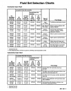
Fluid
Set
Selection
Charts
Using the Charts
Unless otherwise ordered, the Turbine Spray Gun
size
of
the a/r cap, fluid nozzle, and fluid needle are
includes a
1.4
mm fluid set, part no.
M70581.
The
marked on the parts.
Use
the fluid set charts on page
5
to order a different
size
fluid set or to find the part number of an indivi-
dual component of your fluid set. The charts separate
fluid sets that are commonly used in contractor
applications from those commonly used in automotive
applications.
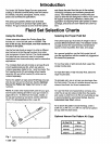
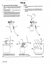
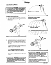
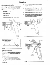
The complete fluid sets
(A)
include an air cap
(a)
and
afluid needlelnozzle set
(C),
which can also be
ordered separately. Refer to Fig.
1
and the charts. The
fluid needlelnoule
(C)
set includes a fluid needle
assembly
(D)
and
a
fluid nozzle
(E),
which can be
ordered separately.
able but are not part of afluid
set.
See the Optional
Narrow fan pattern air caps (wood finishing) are avail-
Narrow Fan Pattern Air Caps chart below for part
numbers.
see the parts drawing and list for your gun model on
NOTE To order other replacement parts for your gun,
pages
20
to
24.
To reference the nozzle, needle, or
air cap part number by
size
alone, see the selection
chart in the Accessories section, page
26.
A
Fig.
1
02981
4
308-336
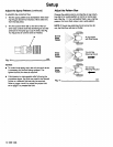
Selecting the Proper Fluid Set
The turbine spray gun fluid sets
(A)
range in size to
provide different fluid flow rates. The selection charts
on page
5
show the recommended combinations
based on fluid viscosities, flow rates, and usage.
As
a general guideline, use the fluid nozzle that will
the lowest fluid pressure.
give the required flow with the needle fully triggered at
For low flow rates
or
light viscosily fluid, select the
smaller nozzle sizes.
For
high
flow rates
or
high viscosity fluid, select the
larger nozzle sizes.
To
eliminate mist, use an air cap one size larger than
the fluid nozzle. The use of a smaller size air cap pro-
duces a finer finish, but it can increase mist.
For very fine finish work (automotive, furniture, etc.),
order the air cap
two
sizes smaller than the needle
and nozzle.
A
0.5M
mm or
0.7M
mm multi-hole air cap
Automotive User
Chart,
above.
is recommended for automotive finishes. See the
For a narrow
fan
pattern (wood finishing), order a
0.5W
mm,
0.7W
mm, or
1
.OW
mm narrow fan pattern
air cap. See the chart below.
Optional Narrow Fan Pattern Air Caps
Alr
Cap
P/N
Slze
M70435
1
.OW
mm
M70441
0.7W
mm
M70438
0.5W
rnm
~